Complete compressed air system.
Combine compression, cooling, treatment, storage and distribution at the required pressure and point-of-use air quality. The layout below explains the system interfaces; it is not a photograph of an installed project.
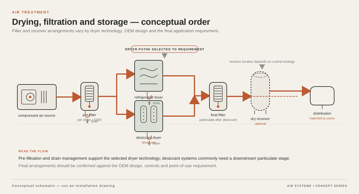
DETAILED SELECTION & OPERATION
What a receiver contributes to the system
The Compressed Air and Gas Institute defines a receiver as a vessel or tank for storing gas under pressure and notes that a large compressed air system may use primary and secondary receivers. In practice, a receiver adds usable storage volume to the system. That volume can cover a brief mismatch between demand and compressor output, allow controls to operate with a wider pressure band, and make intermittent loads less disruptive to the main header. The correct result depends on the demand profile, control method, pressure range and piping arrangement, not on tank volume alone.
Evaluate a receiver with the whole compressed air treatment system. Storage does not establish a pressure dew point or prove point-of-use air purity. The supplier should show how each vessel relates to the compressor, separator, dryer, filters, ring main and drains.
- Buffer short-duration demand peaks rather than cover an indefinitely undersized compressor.
- Separate compressor cycling or load changes from sensitive downstream equipment when controls and pressure limits permit.
- Provide a defined collection and drainage point for condensate where the installation design calls for it.
- Support commissioning.
Primary, secondary and wet-versus-dry placement
A primary receiver is commonly placed near the compressor package or plant header to buffer the general system. A secondary, or point-of-use, receiver can be placed close to a machine with a short high-flow event. That local arrangement may reduce the effect of a pulse on the rest of the network, but it adds valves, drains, supports and inspection points. A piping diagram should identify flow direction, isolation boundaries, non-return protection where needed, and pressure-measurement locations.
Wet and dry receiver describe location relative to air treatment, not a universal tank construction. An upstream receiver is exposed to warmer, wetter air and must be designed into condensate management. A downstream receiver may protect a clean-air branch, but it does not correct an unsuitable treatment train. Ask the supplier to state the sequence and condensate handling at each vessel.
| Item | Why it matters | Confirm before supply |
|---|---|---|
| Primary receiver | Buffers the plant header and compressor control response | Location, volume basis, pressure range and connection arrangement |
| Secondary receiver | Supports a local intermittent or high-flow machine | Peak demand, local pressure target, isolation and drain access |
| Upstream or wet position | Allows condensate collection before drying | Separator, drain, corrosion allowance and treatment sequence |
| Downstream or dry position | Stores treated air for a clean branch | Required air quality, pressure dew point, filter placement and validation |
| Vertical or horizontal arrangement | Changes footprint, supports and access | Foundation, clearance, lifting, inspection and maintenance access |
Size storage from the operating profile, not a rule of thumb
Receiver sizing starts with the event the vessel must manage. Record the minimum and maximum operating pressure, required flow at the event, duration, repetition rate, compressor response time and the pressure allowed at the machine inlet. A short blow-off or actuator pulse has a different storage need from a long shift-level load. A fixed-speed compressor, variable-speed compressor and sequenced multi-compressor plant also respond differently. Industry rules of thumb may be useful for an initial conversation, but they are not a universal design, and they should not be presented as a promised result.
For an RFQ, request the supplier's sizing method and assumptions alongside nominal volume. Ask whether stated flow is FAD, standard flow or actual flow, and specify reference pressure, temperature and humidity. Pressure values must identify gauge or absolute basis. A pressure-decay or fill-time formula is meaningful only when these bases, the usable pressure band and demand event are explicit. Have the supplier check the result against measured demand data or a documented load schedule.
- Continuous base demand and the largest simultaneous intermittent demand.
- Minimum acceptable pressure at the receiver outlet and at the equipment inlet.
- Compressor cut-in, cut-out, modulation or sequencing behavior.
- Required hold-up time, event frequency and recovery time.
- Flow units and reference conditions used in every calculation.
Pressure rating, materials and connections
The requested operating pressure is a buyer requirement, not evidence that this site supplies a particular rating. The vessel's design pressure, maximum allowable working pressure, temperature limits, corrosion allowance, material, weld process, nozzle schedule and connection sizes must come from the proposed manufacturer and be checked against the installation jurisdiction. Do not select a tank only because its nominal pressure exceeds the compressor discharge; relief settings, temperature, transient conditions and every connected component must remain compatible.
Material choice is affected by moisture, ambient conditions, external corrosion exposure and maintenance access. No material option should be assumed from an application name; request the proposed material, corrosion protection and nameplate information.
Safety equipment and jurisdictional compliance
Pressure vessels require a compliance review before purchase. As one US reference, OSHA 29 CFR 1910.169 says new air receivers installed after its effective date are to be constructed to the specified ASME Section VIII edition, and it requires accessible drains, a visible indicating pressure gauge and spring-loaded safety valves with total relieving capacity that limits pressure to no more than 10 percent above the receiver's maximum allowable working pressure. These are not a universal substitute for local law, inspection rules or the vessel manufacturer's instructions.
The RFQ should identify the installation jurisdiction, inspection authority, design or conformity code, documentation language and registration or examination process. Request the relief-device set-point basis, gauge range, drain arrangement and evidence that safety-device capacity matches the vessel and compressor supply. A component certificate alone does not approve the assembled installation. Never bury a receiver or make its access points unreachable.
Installation, treatment and pressure-drop checks
Plan a level, structurally adequate foundation with access for lifting, inspection, draining and valve operation. Protect the vessel from vehicle impact, excessive vibration, heat and external corrosion. Piping supports must not load the nozzles, and isolation arrangements should avoid unsafe trapped pressure. Check pressure drop through valves, separators, filters and branch connections.
Maintenance and condition monitoring
Maintenance frequency depends on the vessel design, ambient humidity, duty cycle, condensate load, coating condition, local rules and the manufacturer's instructions. At minimum, the operating team needs a controlled method to remove accumulated liquid, verify that gauges and relief devices remain serviceable, inspect for corrosion or damage, and preserve records of examinations and repairs. OSHA specifically requires frequent draining at intervals that prevent excessive liquid accumulation; the exact interval must be established for the actual installation rather than invented as a site-wide promise.
Include the receiver in the plant's isolation, lockout and depressurization procedure. Trend pressure behavior and drain performance so a failed drain, leakage, rising pressure drop or changed demand profile is found early. The supplier should identify inspection points and consumables, but the operator remains responsible for the applicable inspection scheme and competent personnel.
RFQ checklist: data to confirm before quotation
A useful quotation request gives the supplier operating and compliance context. Ask for a drawing, support loads, nozzle schedule, pressure and temperature limits, relief-device details, drain arrangement, documentation, exclusions and stated flow and pressure bases. Use this minimum brief and attach measured data where available.
- Site location, applicable pressure-vessel code, inspection authority and required conformity documents.
- Compressor type, rated discharge pressure, control strategy, number of units and sequencing philosophy.
- Measured or estimated base flow, peak flow, event duration, repetition rate and required minimum point-of-use pressure.
- Flow reference condition, pressure basis, temperature and humidity assumptions used for sizing.
- Proposed receiver role and location: primary, secondary, upstream of treatment or downstream of treatment.
- Required volume range, design pressure, operating pressure, design temperature, material and corrosion environment.
- Nozzle sizes and orientation, drain technology, safety valve, gauge, supports, access clearances and foundation loads.
- Delivery scope: vessel only or complete package with valves, instruments, drains, installation, testing and commissioning.
SELECTION & OPERATION
Frequently asked questions
Does a larger air receiver always reduce compressor energy use?
No. Storage can reduce unstable cycling or help separate intermittent demand from compressor control, but the result depends on compressor controls, pressure band, leakage, demand timing and the rest of the system. Request a supplier calculation based on your measured profile rather than assuming a fixed energy saving from tank volume.
Should an air receiver be installed before or after the dryer?
Either arrangement can be appropriate. An upstream receiver can support primary storage before drying. A downstream receiver can store treated air for a clean branch. The supplier must show the treatment sequence and pressure dew point.
What safety devices should be included in an air receiver quotation?
Ask the supplier to identify the pressure gauge, spring-loaded safety valve or other jurisdictionally accepted relief arrangement, drain, isolation provisions, nameplate and required inspection documentation. The exact devices, set points and code evidence must match the vessel and local rules; a generic accessory list is not compliance proof.
Technical references
- Improving Compressed Air System Performance (DOE Sourcebook) ↗
General compressed-air system guidance and receiver storage context; any sizing rule must be treated as a starting point and checked against actual demand and stated reference conditions.
- CAGI Resource Library: Compressed Air Industry Terms ↗
Definitions of receiver, primary and secondary receivers, pressure terms, capacity and standard air reference conditions.
- OSHA 29 CFR 1910.169: Air receivers ↗
US reference requirements covering construction reference, accessible installation, drains, pressure gauge and spring-loaded safety valves; local requirements may differ.