
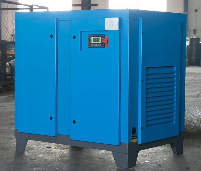
Complete compressed air system.
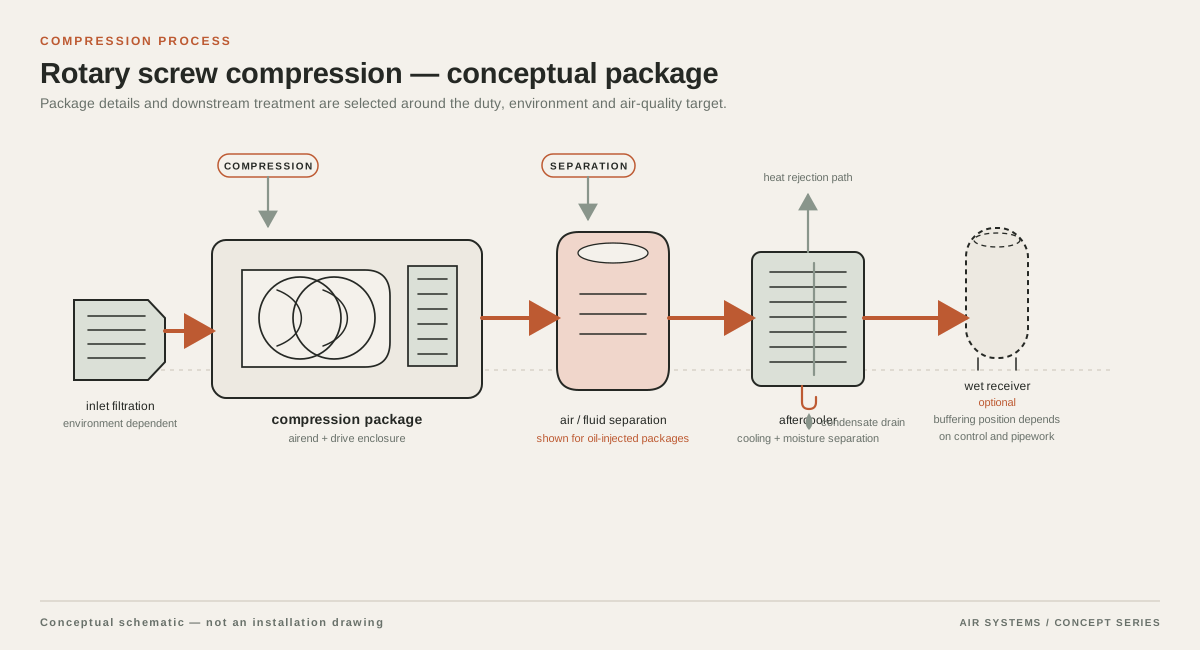
Combine compression, cooling, treatment, storage and distribution at the required pressure and point-of-use air quality. The layout below explains the system interfaces; it is not a photograph of an installed project.
DETAILED SELECTION & OPERATION
Map the factory demand before choosing equipment
Start with an equipment register for every air-consuming point. Record the machine or process, required inlet pressure, flow basis, connection size, duty cycle, operating hours and whether the demand is continuous, cycling or an occasional event. Separate normal production from start-up, changeover, cleaning and maintenance states. A nameplate flow is not automatically the same as measured plant demand, and figures from different suppliers may use different reference conditions. Ask each equipment OEM to state the pressure and flow basis, units, tolerance and minimum pressure at the point of use.
Build a time-based demand profile. Identify loads that run together and short peaks such as simultaneous blow-off or actuator movement. A calibrated flow survey with pressure logging can reveal unloaded running, leaks and instability, but it represents only the observed operating state. Recheck it after production changes. State the pressure, flow basis, units, tolerance and reference conditions for every equipment figure Improving Compressed Air System Performance.
- List continuous, cycling and intermittent users separately.
- Capture simultaneous operation and worst credible production states.
- State FAD, free-air, actual, standard or normal flow reference for every number.
- Record the minimum pressure at the machine inlet, not only compressor discharge pressure.
Design for mixed loads, not an averaged factory
A manufacturing system often needs a stable base supply plus a controlled response to peaks. Multiple central machines may support staging and resilience, while local receivers can reduce short demand bursts. A ring main may provide alternate flow paths and easier isolation, subject to layout, pipe sizing and isolation strategy. These are options to compare, not a requirement for every project.
Avoid adding a blanket margin to an uncertain demand list and calling the result sized. Identify any allowance, tie it to documented expansion or measurement uncertainty, and test it against compressor turndown, standby philosophy and storage response. If one process has a materially different pressure or quality requirement, consider a segregated branch, local booster or dedicated treatment rather than raising the pressure of the whole plant. Higher pressure can increase leakage, so point-of-use requirements should lead the decision.
| Load group | What to establish | Possible design response |
|---|---|---|
| Pneumatic automation | Cycle rate, simultaneous actuators, minimum cylinder pressure and valve exhaust behavior | Stable central supply, correctly sized distribution, local storage where cycles are sharp |
| Assembly and machining tools | Tool inlet pressure, duty factor, torque or process window and hose losses | Point-of-use regulation, suitable filters and short, adequately sized connections |
| Blow-off and cleaning | Nozzle type, open time, user count and whether compressed air is appropriate | Engineered nozzles, timed control, local receiver or an alternative method where suitable |
| Occasional process events | Peak flow, duration, recurrence and effect on other lines | Peak storage, sequencing, dedicated branch or additional staged capacity |
Set pressure from the most demanding point of use
Define a pressure budget from the compressor outlet to the least-favored machine. Include treatment equipment, filters, dryers, valves, flexible hoses, elevation and the distribution network at the specified flow. The compressor discharge setpoint must not be selected simply because a catalogue number is familiar. It should leave enough operating margin for the required point-of-use pressure while avoiding a plant-wide setpoint that compensates for an undersized or poorly configured network.
Use a pressure map with readings at the source, after treatment, at remote headers and at representative machines during peak production. Investigate pressure oscillation separately from a steady pressure drop. A regulator can protect a branch from an excessive upstream pressure, but it cannot create flow capacity. Ask the designer to show pipe material, nominal size, route length, fittings, isolation points, condensate management and future connection points. A final pressure-drop value must be calculated for the proposed layout and stated with its flow and reference assumptions.
Coordinate receivers, controls and resilience
Receivers can buffer short demand changes, provide a place for condensate separation in an appropriate arrangement, and reduce rapid compressor cycling when controls and storage are correctly coordinated. They are not a substitute for adequate generating capacity or an excuse to ignore a sustained deficit. Consider the location and role of wet storage before treatment, dry storage after treatment, and local storage near a peak user. The actual arrangement depends on moisture strategy, pressure limits, control logic and the process risk of a supply interruption.
For multiple compressors, compare lead-lag sequencing, variable-capacity response, standby capacity and service isolation. Ask how the system behaves when one compressor, dryer or electrical feeder is unavailable. A resilience claim should state the assumed production load and actual redundant equipment; do not use N+1 without defining the failure and capacity covered. CAGI’s system-design material treats storage and distribution as integral parts of compressed-air design Compressed Air System Design.
Match treatment to each manufacturing process
Specify air quality by process consequence. General pneumatic automation may have different requirements from instrument air, paint or coating equipment, product-contact operations, electronics assembly or a sensitive measurement process. Define particles, water, oil and microbial or other contaminants only where the process owner has established limits. Select compressed air treatment equipment as a coordinated train: aftercooling and condensate handling, filtration, drying, drains and point-of-use protection each have a role. Do not assume that a compressor described as oil-free automatically establishes a finished-air quality or product-safety result.
Check installation, heat and environment
The compressor room needs a layout that supports safe access, intake air quality, cooling-air movement, condensate routing, lifting, service clearances and noise management. Confirm ambient temperature range, altitude, dust, corrosive vapors and seasonal conditions with the supplier. Heat rejection and ventilation should be calculated for the proposed equipment and operating state; a nominal room size is not a ventilation design. Keep intake air away from vehicle exhaust, process vapors and sources that could contaminate the compressor or treatment train.
Trace utilities beyond the compressor: electrical fault level and starting method, isolation, controls network, drains, wastewater handling, lifting, foundations and pipe supports. Plan isolation and depressurization points so maintenance does not require improvisation. Receiver installation and inspection are jurisdiction-specific. For example, U.S. OSHA 1910.169 addresses accessible installation, draining, a visible pressure gauge and spring-loaded safety valves; applicable local pressure-vessel rules must govern other projects OSHA Air receivers.
Make maintenance and verification part of the design
Request a maintenance plan based on selected equipment, ambient conditions, operating hours, loading pattern and supplier instructions. It should identify service access, consumables, filter and dryer checks, drain testing, leak surveys, sensor verification, relief-device inspection and safe isolation. No universal interval is valid for every compressor or factory. Include a method for recording treatment differential pressure and source and point-of-use pressure during comparable production states.
Commissioning should verify the installed system against the approved design basis. Witness flow and pressure at representative remote points, dryer performance at specified load and ambient condition, control sequencing, condensate handling, alarms and recovery after a defined peak. Record instrument accuracy, test conditions and temporary bypasses. Acceptance should distinguish manufacturer equipment data from plant-level results measured after installation.
RFQ criteria for a manufacturing compressed-air system
An RFQ should make the operating envelope clear for supplier comparison. Ask for a proposed architecture and marked-up basis of design, not just a motor rating. Require all flow and pressure figures to state reference basis, temperature, humidity assumptions and measurement location. Ask suppliers to identify exclusions and assumptions, including expansion, standby duty, treatment bypasses, drainage and civil or electrical interfaces.
Include these criteria in the quotation request:
Require a data-to-confirm notice for every item that depends on site conditions or supplier selection. This prevents an indicative arrangement from being mistaken for a confirmed product specification.
Compare lifecycle and operational consequences as well as purchase price. The lowest quoted package may create a pressure bottleneck, unsuitable air quality, difficult maintenance access or poor response to intermittent peaks.
- Measured or estimated demand profile, loads, production states and expansion.
- Required pressure at each critical point, pressure-drop budget and clearly stated flow reference conditions.
- Compressor arrangement, capacity control, sequencing, standby philosophy, receiver roles and recovery expectations.
- Air-quality targets by branch, treatment stages, rated flow, pressure drop, drains and bypass strategy.
- Site ambient conditions, room ventilation, electrical supply, controls integration, noise limits and service clearances.
| Item | Often considered | Confirm with supplier and site owner |
|---|---|---|
| Compressors | Multiple machines and a control method | Capacity at required conditions, turndown, sequencing, standby and electrical interfaces |
| Storage | Central and/or local receiver | Usable volume, pressure rating, location, condensate and compliance |
| Treatment | Dryer, filters and drains | Quality target, flow basis, pressure drop, ambient limits and maintenance |
| Distribution | Header or ring main | Pipe calculations, remote pressure, isolation, supports and future branches |
| Controls | Controller and pressure sensors | Signals, alarms, data retention and owner integration |
| Documentation | Manuals and commissioning records | Drawings, datasheets, tests, certificates, inspection and training |
When a general manufacturing design needs a separate branch
A plant dominated by one steady, high-load process needs a different capacity study from a facility with many intermittent users. Use the load profile and process risk to decide whether a common header, dedicated branch, booster or local receiver is appropriate.
SELECTION & OPERATION
Frequently asked questions
How should a factory size compressed air capacity for mixed manufacturing loads?
Create a load register and time-based profile first. Test simultaneous demand against point-of-use pressure, treatment drop, storage response, control range and standby philosophy. State every flow reference condition and identify expansion allowance separately. Motor size alone is not a capacity specification.
Is one central compressor enough for a manufacturing plant?
It depends on demand diversity, interruption risk, layout and maintenance strategy. Multiple staged compressors, central storage and local receivers may improve response or resilience, while a dedicated branch may suit a high-pressure or sensitive process. Require the proposed architecture and defined outage behavior.
What air treatment does general manufacturing require?
Define particle, water and oil limits from each process, then select drying, filtration, drains and point-of-use protection for the stated flow and conditions. Oil-free compression is not a finished-air quality or product-safety guarantee. Require pressure-drop and validation information.
What should be included in an RFQ for a manufacturing compressed-air system?
Include demand states, point-of-use pressures, flow bases, quality targets, site conditions, electrical and room interfaces, distribution, storage, standby, controls, commissioning, documentation and maintenance assumptions. Label site-dependent items subject to confirmation.
Technical references
- Improving Compressed Air System Performance ↗
System assessment, storage, controls, leakage and inappropriate-use topics for industrial compressed-air planning.
- Compressed Air System Design ↗
Design treatment of storage, receivers and distribution as parts of the complete compressed-air system.
- OSHA Air receivers ↗
U.S.-specific examples of air-receiver accessibility, draining, pressure gauge and safety-valve requirements; local law must be checked for other jurisdictions.