INDUSTRIAL COMPRESSOR EQUIPMENT

Rotary Screw Air Compressors

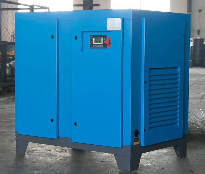
Compare fixed-speed, variable-speed and two-stage electric rotary screw compressor configurations for a defined plant-air duty. The catalogue material documents stationary LG / LGⅡ and EB/BPLG / EB/BPLGⅡ series, plus electric mobile YLG arrangements. The shown photos are catalogue references for the normal-air compressor family, not proof that a pictured enclosure is the listed model. Select the final package around required discharge pressure, nominal flow, control response, electrical supply, cooling, air treatment, storage and installation conditions.

  • Fixed-speed, variable-speed and Ⅱ-coded two-stage configuration paths
  • Documented pressure rows from 5–18 bar (0.5–1.8 MPa)
  • Catalogue nominal-flow rows up to 110 m³/min; final duty is confirmed per model
  • Existing stationary and electric mobile normal-air equipment photographs
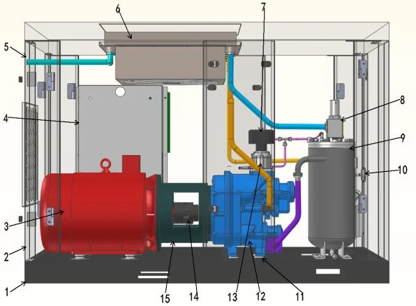
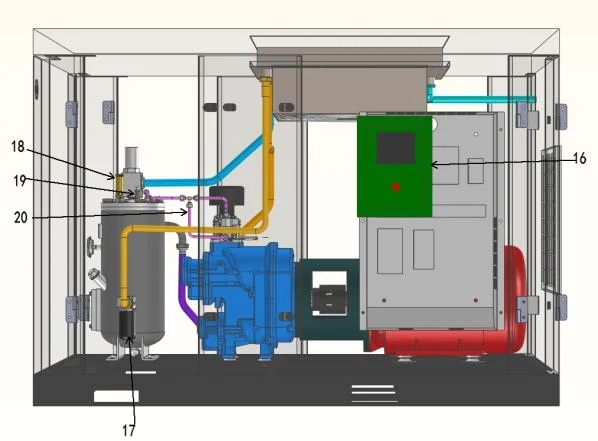
  • Structure diagrams retained as technical illustrations, not product photographs

Choose a configuration.

01

Electric rotary screw compressor series documented in the catalogue

The normal-air electric catalogue documents three relevant configuration paths for this page: fixed-speed LG, variable-speed EB/BPLG and Ⅱ-coded two-stage configurations in both families. The original model key identifies Ⅱ as second-stage compression. The clean specification tables above select confirmed rows from the fixed-speed, variable-speed and two-stage tables so that a small 6 bar example is not used to represent the whole documented range.

Across the cited normal-air tables, confirmed rows cover 5–18 bar (0.5–1.8 MPa), 7.5–560 kW motor power and 0.8–110 m³/min nominal flow. These are catalogue entries, not a single operating envelope for every model: pressure, nominal flow and motor power must be read together from one row. The manual also lists YLG / YLGⅡ electric mobile arrangements; use the electric mobile image as a configuration reference only, not as proof of a particular listed model.

  • LG fixed-speed family: compare a fixed-speed package where the measured plant load is a stable base duty.
  • EB/BPLG variable-speed family: compare variable-speed control where demand changes materially during operation and the usable control range fits the measured profile.
  • Ⅱ-coded rows: the manual identifies the Ⅱ designation as two-stage compression; fixed-speed LGⅡ and variable-speed EB/BPLGⅡ examples are shown separately in the catalogue table.
  • The normal-air manual describes its compressor series as micro-oil screw compressors; it does not identify an oil-free compressor model for this page.

EQUIPMENT CONFIGURATIONS

Compare the series specifications.

Compare the listed pressure and flow basis, then send the application and operating profile for a matched quotation.

LG fixed-speed series — representative catalogue models
Catalogue modelMotor rated power (kW)Discharge pressureNominal flow (m³/min)
LG-1.1/8-7.57.58 bar (0.8 MPa)1.1
LG-2/6-11116 bar (0.6 MPa)2
LG-1/16-151516 bar (1.6 MPa)1
LG-1.5/17-222217 bar (1.7 MPa)1.5
LG-7/18-757518 bar (1.8 MPa)7
LG-20/17-18518517 bar (1.7 MPa)20
LG-42/6-2202206 bar (0.6 MPa)42
EB/BPLG variable-speed series — representative catalogue models
Catalogue modelMotor rated power (kW)Discharge pressureNominal flow (m³/min)
EB/BPLG-1.1/8-7.57.58 bar (0.8 MPa)1.1
EB/BPLG-2/6-11116 bar (0.6 MPa)2
EB/BPLG-1/16-151516 bar (1.6 MPa)1
EB/BPLG-1.5/17-222217 bar (1.7 MPa)1.5
EB/BPLG-7/18-757518 bar (1.8 MPa)7
EB/BPLG-20/17-18518517 bar (1.7 MPa)20
EB/BPLG-42/6-2202206 bar (0.6 MPa)42
Ⅱ-coded two-stage series — fixed and variable-speed representative catalogue models
Catalogue configurationCatalogue modelMotor rated power (kW)Discharge pressureNominal flow (m³/min)
LGⅡ fixed-speedLGⅡ-3/8-15158 bar (0.8 MPa)3
LGⅡ fixed-speedLGⅡ-7.3/6-30306 bar (0.6 MPa)7.3
LGⅡ fixed-speedLGⅡ-7/14-555514 bar (1.4 MPa)7
LGⅡ fixed-speedLGⅡ-16/17-13213217 bar (1.7 MPa)16
LGⅡ fixed-speedLGⅡ-37/6-1601606 bar (0.6 MPa)37
LGⅡ fixed-speedLGⅡ-62/5-2502505 bar (0.5 MPa)62
LGⅡ fixed-speedLGⅡ-110/5-5005005 bar (0.5 MPa)110
LGⅡ fixed-speedLGⅡ-108/8-5605608 bar (0.8 MPa)108
EB/BPLGⅡ variable-speedEB/BPLGⅡ-3/8-15158 bar (0.8 MPa)3
EB/BPLGⅡ variable-speedEB/BPLGⅡ-7.3/6-30306 bar (0.6 MPa)7.3
EB/BPLGⅡ variable-speedEB/BPLGⅡ-7/14-555514 bar (1.4 MPa)7
EB/BPLGⅡ variable-speedEB/BPLGⅡ-16/17-13213217 bar (1.7 MPa)16
EB/BPLGⅡ variable-speedEB/BPLGⅡ-37/6-1601606 bar (0.6 MPa)37
EB/BPLGⅡ variable-speedEB/BPLGⅡ-62/5-2502505 bar (0.5 MPa)62
EB/BPLGⅡ variable-speedEB/BPLGⅡ-110/5-5005005 bar (0.5 MPa)110
EB/BPLGⅡ variable-speedEB/BPLGⅡ-108/8-5605608 bar (0.8 MPa)108

Catalogue basis: selected rows from the fixed-speed table; flow is the source table’s nominal m³/min and is not labelled FAD; the adjacent source note lists 1 atm, ambient ≤40°C and 50% relative humidity; motor rated power is not package electrical input.

Catalogue basis: selected rows from the variable-speed fixed table; flow is the source table’s nominal m³/min and is not labelled FAD; motor rated power is not package electrical input.

Catalogue basis: the original model key defines Ⅱ as second-stage compression; flow is the source table’s nominal m³/min and is not labelled FAD; motor rated power is not package electrical input.

Source: Electric atmospheric-pressure compressor selection manual (电动常压选型手册-.pdf) · pp. 4, 5, 6, 8; Electric atmospheric-pressure compressor selection manual (电动常压选型手册-.pdf) · pp. 10, 11, 12, 14; Electric atmospheric-pressure compressor selection manual (电动常压选型手册-.pdf) · pp. 4, 5, 6, 7, 8, 9, 10, 11, 12, 13, 14, 15, 16. Final model duty and supply scope are stated in the quotation.

02

Choose a configuration before requesting a model quotation

A fixed-speed package is commonly evaluated for a stable base load, while a variable-speed package may be evaluated where demand changes materially during a shift. These are comparison categories, not claims about a universal energy result. A variable-speed drive still has a usable operating range, minimum speed, motor limits and control response that must be confirmed. A fixed-speed unit can also operate in a sequenced multi-machine system, where several machines share base and trim duties.

The motor-power values in the catalogue tables are motor rated power; they are not package electrical input. Ask the supplier to state package-specific input power and delivered flow at the proposed discharge pressure, including the test method, reference conditions and whether power is full-load, part-load, unloaded or standby. Avoid comparing energy numbers taken at different pressures, flow bases, ambient conditions or unloaded states.

Ask the supplier to explain the control sequence at low demand, during rapid peaks and when one package is unavailable. Check how inlet modulation, start-stop, load-unload or speed control affects delivered flow and power. Review pressure-band settings and whether a local controller, plant master controller or building management system will be the decision-maker.

Configuration comparison for RFQ planning; final model and package scope are confirmed in the quotation
Catalogue familyDocumented formSelection questions
LG / LGⅡFixed-speed electric stationary rows; Ⅱ is the manual’s two-stage designationMeasured base load, sequencing role, discharge pressure, cooling and service access
EB/BPLG / EB/BPLGⅡVariable-speed electric stationary rows; Ⅱ is the manual’s two-stage designationUsable control range, minimum speed, response to peaks, controls interface and duty profile
YLG / YLGⅡElectric mobile arrangements listed in the same normal-air manualMobility need, power supply, towing or placement constraints and final site duty
Cooling and treatmentAir-cooled or water-cooled arrangement with separate or integrated downstream equipmentHeat rejection, ventilation or cooling-water duty, pressure drop, drains, dew point and air-quality requirement

COMPONENT ARRANGEMENT

Package components.

Catalogue structure diagrams show the arrangement of compression, controls and cooling. Check clearances and installation scope for your chosen configuration.

Catalogue schematic of the screw compressor package with numbered component locations.
Product structure diagramCatalogue component layout — structure diagram, not a photograph.
Catalogue schematic showing the motor, compression block and cooling arrangement.
Product structure diagramCatalogue component layout — structure diagram, not a photograph.
03

Specify the package, pressure, flow and treatment as one system

Rotary screw packages may use an oil-injected compression process or an oil-free compression process. In an oil-injected arrangement, the fluid can support sealing and cooling inside the compression stage, followed by separation and treatment. In an oil-free arrangement, the compression process is designed without oil introduced into the compression chamber, but the complete installation can still have contamination sources in ambient intake air, piping, seals, coolers, condensate or downstream equipment.

Select the compression process after defining the end-use quality requirement. Food, pharmaceutical, electronics, paint and instrument-air users should identify the applicable contamination limits, sampling method and point of measurement instead of treating “oil-free” as a blanket product or process guarantee. ISO 8573-1 is a classification framework for contaminants and purity classes; the relevant class, test evidence and treatment train must be specified for the application. A component certificate does not by itself approve the complete assembly or prove point-of-use quality.

Begin with the pressure required at the consuming equipment, then add only the losses and control margin that are justified by the installation design. Do not raise compressor pressure simply to compensate for an unknown restriction. State whether pressure is gauge or absolute, and identify the normal, minimum and peak values. The catalogue flow values on this page retain the manual’s nominal m³/min designation; they are not stated as FAD. Values using different reference bases are not directly interchangeable.

Air quality should be written as an end-use requirement, not as a marketing adjective. Identify particles, water and oil limits, pressure dew point, filtration location and the required verification method. Treatment may include aftercooling, separators, filters, dryers, drains and point-of-use equipment. The compressor outlet, storage vessel outlet and point of use can have different conditions. Include the most demanding user without assuming that the entire plant needs the same treatment if a segregated branch is technically acceptable.

An aftercooler can reduce discharge temperature and allow condensate separation, but it does not replace a dryer when the process requires a defined pressure dew point. Filters must be selected for the contaminant and flow duty, and their pressure drop and drain arrangement should be included in the review. Automatic drains, condensate handling and discharge routing need local environmental and safety checks.

A receiver can buffer short demand changes, reduce rapid control cycling and provide a stable measurement location, but its useful role depends on demand shape, pressure band and control logic. It is not a substitute for adequate compressor capacity or a cure for distribution losses. Confirm vessel code, inspection, relief protection, isolation and drain requirements for the installation jurisdiction.

04

Where a rotary screw compressor fits

A screw package is often considered when a plant has a steady base load, repeated shifts or many pneumatic users operating at the same time. Its positive-displacement rotors deliver a continuous stream rather than the discrete strokes associated with a reciprocating machine. That does not make every screw package the right choice: a small, intermittent demand may be better served by a different arrangement, while an installation with large short peaks may need storage, sequencing or a supplementary machine.

The correct comparison is the complete system at the required operating point. Review actual demand over a representative production period, including unloaded or idle time, start-up events, leaks and future expansion. A nominal motor size is not a substitute for flow data. CAGI describes standardized data sheets as a way to compare relevant compressor performance information, while noting that energy is a major life-cycle cost consideration.

  • Appropriate starting point: recurring plant demand with a defined pressure band and enough operating hours to justify a packaged rotary solution.
  • Use caution when demand is highly intermittent, unusually low, rapidly changing or dominated by short peaks.
  • Do not infer suitability from the compressor family name alone; verify flow, pressure, control range and air quality together.
05

Plan installation, cooling and maintenance before ordering

Reserve access for filters, separators, coolers, belts or couplings where applicable, oil or condensate service, electrical equipment and lifting or replacement. Confirm the floor, foundation, vibration limits, intake location and discharge routing. An air-cooled package adds heat to the room; a water-cooled package adds water-side requirements. Intake air should be clean enough for the chosen process, and the room should prevent recirculation of hot exhaust air into the compressor inlet.

The distribution design should separate production requirements from local equipment preferences. Check pipe size, branch arrangement, isolation points, ring-main strategy, elevation changes, drains and point-of-use regulators. Measure or estimate pressure drop across the full route at the specified flow, including dryers, filters, valves and flexible connections. For multiple compressors, document sequencing, common receiver location and the effect of an isolated machine on minimum plant pressure.

Maintenance requirements depend on the compressor design, OEM instructions, ambient conditions, operating hours, load profile and the condition of intake and treatment components. A quotation should identify service access, consumables, inspection points, instrumentation and the records needed to maintain warranty or compliance. Do not use a universal service interval or predicted lifespan without the specific manual and duty assumptions.

Compare more than purchase price. Request a clear separation of full-load, part-load, unloaded and standby power where relevant, plus the assumptions behind any annual energy estimate. CAGI’s verification program explains that published rotary-compressor data sheets are intended to support comparison and that performance testing uses specified methods; participation and verification must still be checked for the exact quoted model. Include energy, treatment consumables, condensate disposal, planned service, downtime exposure and replacement strategy in the lifecycle review.

Complete compressed air system.

Combine compression, cooling, treatment, storage and distribution at the required pressure and point-of-use air quality. The layout below explains the system interfaces; it is not a photograph of an installed project.
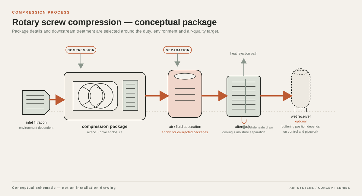
Conceptual supply arrangement for Rotary Screw Air Compressors
System schematic. Component sequence depends on the selected equipment and duty.

DETAILED SELECTION & OPERATION

06

RFQ checklist: data to confirm before selection

A technically useful RFQ lets suppliers price and size the same duty. Send a demand profile rather than only a desired motor rating. Include the process, operating hours, shift pattern, present compressor inventory, measured flow and pressure, expansion allowance, site conditions and the strictest air-quality requirement. Ask each respondent to identify exclusions, assumptions and deviations so apparent comparisons do not hide different system boundaries.

For a quoted catalogue model, confirm the final model code, rated motor power, delivered flow at the proposed pressure, flow reference basis, package input power, control range, sound level, certification scope, included treatment, service commitment, warranty term, price and delivery date in the supplier’s current quotation and supporting documents.

  • Demand: measured average, minimum, peak and short-duration flow; operating hours; shift pattern; simultaneous users; future expansion.
  • Pressure: point-of-use minimum, normal and maximum; compressor discharge target; gauge or absolute basis; estimated distribution and treatment losses.
  • Site: altitude, ambient temperature range, humidity, room ventilation, electrical supply, cooling water, footprint, lifting route and noise constraints.
  • Quality: particle, water and oil limits; pressure dew point; point of measurement; sampling and verification plan; condensate requirements.
  • Commercial and service: included equipment, exclusions, commissioning scope, spares, maintenance assumptions, warranty, documentation and lead-time basis.

SELECTION & OPERATION

Frequently asked questions

What pressure and flow range is documented for these rotary screw series?

The cited fixed-speed and variable-speed normal-air tables include confirmed rows from 5 to 18 bar (0.5 to 1.8 MPa), with nominal flow entries from 0.8 to 110 m³/min and motor-power entries from 7.5 to 560 kW. Those are catalogue-table values, not a single duty point applicable to every model. Read pressure, nominal flow and motor power together from the selected row, then confirm the final duty in the quotation.

What does the Ⅱ designation mean in the listed screw compressor models?

The original manual’s model key identifies Ⅱ as second-stage compression. The catalogue therefore shows LGⅡ fixed-speed and EB/BPLGⅡ variable-speed two-stage examples separately from other listed configurations. Confirm the full package arrangement, control and selected pressure at quotation stage.

Are rotary screw air compressors suitable for every factory?

No. They are a candidate for recurring industrial demand, but suitability depends on flow, pressure, duty cycle, control range, air quality, cooling and installation constraints. A highly intermittent or very small load may need a different configuration, storage strategy or a mixed compressor arrangement.

Should I choose an oil-free screw compressor whenever air contacts a product?

Not automatically. First define the applicable air-quality limits and verification method at the point of use. Oil-free compression addresses one part of the contamination question; intake air, piping, treatment, seals and maintenance can still affect the complete system. Confirm the required ISO 8573-1 class and evidence for the actual assembly and application.

What flow information should appear in a screw-compressor quotation?

The quotation should state delivered flow at the proposed pressure, the test or rating method, and the reference pressure, temperature and humidity. If it uses FAD, CFM or normalized flow, define the basis. The catalogue tables on this page use nominal m³/min and do not label it FAD. Also request package power at the same operating point and clarify whether the figure is full-load, part-load, unloaded or standby power.

Does adding a receiver allow me to buy a smaller compressor?

A receiver can buffer short peaks and support control stability, but it cannot replace sustained capacity. Its effect depends on demand duration, pressure band, allowable pressure variation, receiver volume and control logic. Have the supplier model the load profile and confirm vessel safety, relief protection, inspection and drain requirements for the installation jurisdiction.

Technical references

  1. Dezhou YITong / Yilifang Machinery ↗

    Company identity and authorized use of the normal-air catalogue material; model rows are transcribed from the supplied electric atmospheric-pressure selection manual.

  2. Improving Compressed Air System Performance: A Sourcebook for Industry ↗

    General rotary screw compressor characteristics, cooling options and system-performance improvement context.

  3. CAGI Performance Verification ↗

    Use of standardized rotary-compressor data sheets, performance verification context, ISO 1217 test references and the importance of comparing energy-related data at stated conditions.

  4. ISO/TC 118/SC 4 Standards Catalogue ↗

    ISO 8573-1 as the compressed-air contaminants and purity-classes framework and the existence of separate contaminant measurement parts.

PROJECT QUOTATION

Specify your air system.

Send the working pressure, air demand and operating conditions. We will help select equipment and system components for your process.

Send your project requirements ↗