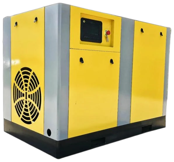
INDUSTRIAL COMPRESSOR EQUIPMENT

40 Bar Air Compressors

Review electric medium/high-pressure catalogue examples at the top of this page, then define the system components around a documented 40 bar duty. The retained entries show a 4.0 MPa discharge-pressure cell and nominal m³/min flow designation; they do not set receiver, treatment or point-of-use conditions. Use the source-backed comparison with continuous and peak demand information to prepare an RFQ that keeps cooling, storage and downstream pressure ratings in scope.

  • 4.0 MPa catalogue entries presented as 40 bar for comparison
  • Nominal volume flow retained in the source m³/min designation
  • Cooling, receiver and treatment selected as a rated system
  • Continuous demand separated from peak-event recovery
01

4.0 MPa electric medium/high-pressure catalogue models

The electric medium/high-pressure catalogue's model-code guide states an H medium-pressure range of 1.6–4.0 MPa. In the parameter table, the models retained here carry a /40 code and show a discharge-pressure cell of 4 under the MPa heading; this page formats that confirmed value as 40 bar (4.0 MPa). The catalogue table above is intentionally limited to those clean, corroborated entries.

The source guide describes LG as a screw-and-scroll integrated unit. It also uses II as a two-stage compression code, while the first-stage code I is omitted. The listed 4.0 MPa entries therefore use EBLG+DLG or EBLGII+DLG notation. The code guide is useful for comparing compression architecture, but it does not define the final piping, controls, cooler, receiver, dryer, filters or site utilities for every project.

Catalogue nominal volume flow is shown exactly with the source designation m³/min. It is not relabelled as FAD, and motor rated power is not package electrical input. Compare model values only after agreeing the flow reference conditions and the required pressure at the point of use. See the air-flow reference guide for the shared terminology.

  • Confirmed pressure presentation on this page: 40 bar (4.0 MPa).
  • Confirmed catalogue flow label: nominal volume flow, m³/min; no FAD claim is made.
  • Confirmed catalogue power label: motor rated power, kW; it is not total package input power.

EQUIPMENT CONFIGURATIONS

Compare the series specifications.

Compare the listed pressure and flow basis, then send the application and operating profile for a matched quotation.

Electric medium/high-pressure catalogue — 40 bar (4.0 MPa) models
Catalogue modelRated discharge pressureNominal volume flow (m³/min; source designation)Motor rated power (kW)
EBLG+DLG-6/40-75Kw40 bar (4.0 MPa)675
EBLGII+DLG-10/40-132Kw40 bar (4.0 MPa)10132
EBLGII+DLG-12/40-160Kw40 bar (4.0 MPa)12160
EBLGII+DLG-14/40-185Kw40 bar (4.0 MPa)14185
EBLGII+DLG-16/40-185Kw40 bar (4.0 MPa)16185
EBLGII+DLG-18/40-200Kw40 bar (4.0 MPa)18200
EBLGII+DLG-20/40-200Kw40 bar (4.0 MPa)20200
EBLGII+DLG-22/40-220Kw40 bar (4.0 MPa)22220
EBLGII+DLG-24/40-240Kw40 bar (4.0 MPa)24240
EBLGII+DLG-26/40-265Kw40 bar (4.0 MPa)26265

Catalogue basis: the model-code guide gives an H medium-pressure range of 1.6–4.0 MPa, and the retained source-table rows show 4 under the discharge-pressure (MPa) heading; this table presents that confirmed value as 40 bar (4.0 MPa). Flow retains the source designation nominal volume flow (m³/min), not FAD; motor rated power is not package electrical input.

Source: Dezhou YITong electric medium/high-pressure selection catalogue (电动中高压选型手册-.pdf) · pp. 3, 6, 7, 8. Final model duty and supply scope are stated in the quotation.

02

Compression and system configurations to compare

A 4.0 MPa duty should begin with the pressure band that the process actually needs, not with a motor size. The catalogue code differentiates an LG integrated screw-and-scroll notation from LGII notation with a two-stage compression code. That describes the compression code in the source, rather than proving a universal package arrangement or a particular application fit.

Where high pressure is needed only at one machine, compare a dedicated 40 bar package with a lower-pressure source feeding a booster and with a separate high-pressure branch. A booster arrangement can be worth evaluating for limited or intermittent demand; a dedicated package may be considered when the 4.0 MPa demand is substantial or sustained. The proposal needs to state its inlet conditions, discharge pressure, delivered flow basis, control sequence and heat rejection rather than relying on the word booster alone.

40 bar configuration questions
Configuration to evaluateWhat the source or system concept establishesQuestions for the RFQ
EBLG+DLG catalogue codeLG is described in the catalogue code guide as an integrated screw-and-scroll unit; the 6 m³/min, 75 kW /40 entry uses this notation.Confirm the final compression arrangement, cooling medium, controls, package boundary and delivered flow at 4.0 MPa.
EBLGII+DLG catalogue codeLGII includes the catalogue's II two-stage compression code; the retained /40 entries cover 10–26 m³/min and 132–265 kW nominal values.Confirm stage operating limits, interstage or final cooling, control range, pressure protection and the conditions behind the published values.
Lower-pressure source plus boosterA system architecture to compare when the high-pressure branch has limited or intermittent demand; it is not represented as a specific catalogue model in the table.State booster inlet pressure and quality, peak recovery time, receiver location, isolation and how the upstream source behaves during the event.

COMPONENT ARRANGEMENT

Package components.

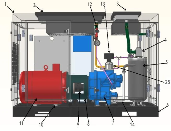
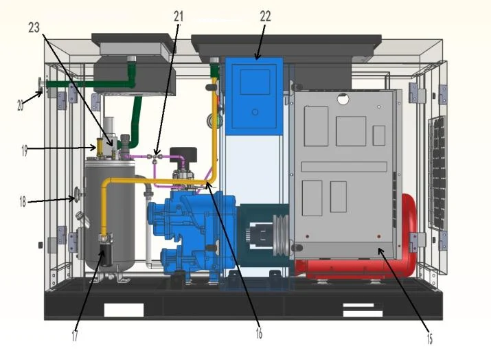
Catalogue structure diagrams show the arrangement of compression, controls and cooling. Check clearances and installation scope for your chosen configuration.

High-pressure compressor catalogue structure diagram showing motor, compression unit and piping.
Product structure diagramCatalogue structure diagram. Confirm the selected package layout.
High-pressure compressor catalogue diagram showing controls, oil filter and piping layout.
Product structure diagramCatalogue structure diagram. Confirm the selected package layout.
03

Build the 40 bar package around cooling, storage and treatment

For the retained 4.0 MPa catalogue rows, the source table distinguishes discharge temperature without aftercooling (≤95°C) from a separately installed aftercooler condition (≤ ambient +20°C). Use those values only as catalogue conditions. They do not replace a project heat-load calculation, ventilation or cooling-water design, nor do they establish the discharge temperature after an actual installation.

A typical system review follows the pressure boundary from compressor discharge through aftercooling, condensate separation and draining, high-pressure storage, isolation and relief protection, drying and filtration, then distribution to the point of use. The receiver and every pressure-containing item need a documented design and operating rating suitable for the selected pressure, temperature and local rules. Receiver volume may soften a short event; it is not a substitute for sustained compressor capacity.

Choose dryers and filters from the actual inlet pressure, temperature, flow reference, pressure drop, drain behaviour and required point-of-use air quality. If air contacts a product or a critical surface, specify the required particle, water and oil classes and a verification method at that point of use. A 40 bar catalogue model, aftercooler or filter train does not by itself establish food, PET or other process-air quality.

  • Check the maximum working pressure and temperature of the cooler, separator, receiver, valves, hoses, dryer, filters and instruments—not just the compressor discharge rating.
  • Provide condensate management and maintenance access in the equipment layout.
  • Request the pressure loss of each treatment item at the stated flow and condition.
04

Applications to assess against a documented 4.0 MPa duty

These 40 bar model entries can be considered for a documented high-pressure branch such as an OEM-specified blowing operation, a pressure or leak-test station, or specialist process equipment with a defined 4.0 MPa inlet requirement. The process document must still identify the required flow, permitted pressure variation, cycle and air-quality condition at the machine inlet.

For PET bottle blowing, separate the high-pressure blowing event from low-pressure auxiliaries such as actuators, conveying and general plant air. Compare direct high-pressure compression and a booster architecture around the bottle, machine, throughput and recovery profile; neither the /40 code nor a single 4.0 MPa entry proves a fit for every PET line. Review the PET bottle blowing system page for the application-specific brief.

  • Start with the OEM pressure band at the machine inlet, not a headline pressure alone.
  • Keep high-pressure and ordinary plant-air loads in separate demand profiles where appropriate.
  • Set point-of-use cleanliness requirements for the specific process rather than applying a blanket air-quality promise.
05

Install and maintain the complete pressure system

Place the package so cooler airflow or cooling-water connections, drains, electrical access, lifting, service clearances and discharge routing can be maintained safely. The final layout should show the compressor or booster discharge, cooling and separation equipment, receiver, drains, relief devices, isolation points, treatment train and point-of-use pressure measurement. Confirm that piping, hose assemblies, fittings and instruments are selected for the system's pressure and temperature conditions.

Maintenance intervals and consumables depend on the final technology, operating hours, ambient conditions, lubricant or dry-running design, water quality where applicable, control behaviour and treatment loading. Ask for the exact model's OEM maintenance schedule, inspection points, drain service, cooler cleaning procedure, filter and dryer service, alarms and commissioning checks. Do not transfer an interval from a different pressure or duty configuration.

Complete compressed air system.

Combine compression, cooling, treatment, storage and distribution at the required pressure and point-of-use air quality. The layout below explains the system interfaces; it is not a photograph of an installed project.
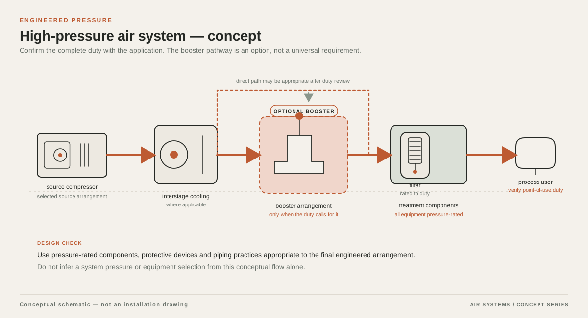
Conceptual supply arrangement for 40 Bar Air Compressors
System schematic. Component sequence depends on the selected equipment and duty.

DETAILED SELECTION & OPERATION

06

Separate sustained demand from short peaks

The catalogue table gives nominal flow and motor rated power; it does not state a project-specific continuous-duty or peak-response guarantee. For sustained 4.0 MPa demand, evaluate delivered flow at the agreed pressure and reference conditions together with control range, cooling capacity and allowable operating limits. For short demand events, record peak flow, duration, repetition rate, simultaneous users, usable receiver pressure band and acceptable recovery time.

Do not size a system by multiplying the largest connected load by an unexplained diversity factor. A high-pressure receiver can buffer a defined event when its usable pressure swing, absolute-pressure basis, temperature and recovery are considered. It cannot make an undersized compressor meet continuous demand. The air receiver sizing guide and pressure-drop guide cover the shared principles without repeating them here.

  • Normal flow at the point of use and its stated reference basis.
  • Peak flow, event duration, events per hour and simultaneous demand.
  • Minimum process inlet pressure, maximum permitted pressure and recovery target.
  • Control sequence and the upstream behaviour if a booster is part of the proposal.
07

Illustrative 40 bar selection brief: continuous flow and a peak event

This is a teaching example, not a recommendation of a catalogue model. Assume one 4.0 MPa process branch needs 10 m³/min continuously and rises to 14 m³/min for 45 seconds once every 10 minutes. Assume all quantities use one stated, hypothetical common reference condition; they are not asserted to be FAD. Assume the process requires at least 3.7 MPa at its inlet and the site has separately defined ambient, electrical and cooling conditions.

The additional event flow is 4 m³/min for 45 seconds. Its time-average contribution is 4 × 45 ÷ 600 = 0.30 m³/min, making the example's time-average demand 10.30 m³/min. The instantaneous requirement during the event is 14 m³/min. Neither number can be matched directly to the source table's nominal-flow label: first reconcile the flow bases, treatment losses, receiver pressure swing, recovery time and the delivered-flow evidence at the required discharge pressure.

The RFQ should ask the supplier to show whether the compressor supplies the sustained component, how any receiver covers the 45-second event, how quickly pressure recovers, and what happens if the event repeats early or overlaps another load. It should also state the required maximum pressure, treatment pressure loss, downstream component ratings and commissioning measurements.

Teaching assumptions for a 4.0 MPa selection brief
ItemAssumed input or calculationWhy it matters
Normal process demand10 m³/min continuously at one stated hypothetical reference conditionForms the sustained capacity check; it is not automatically FAD.
Peak event14 m³/min for 45 seconds, once every 600 secondsSets the instantaneous flow and receiver/recovery assessment.
Average event increment(14 − 10) × 45 ÷ 600 = 0.30 m³/minShows why a time average does not replace a peak-demand check.
Time-average demand10 + 0.30 = 10.30 m³/minA planning input only; final selection needs a matching flow basis and delivered-flow evidence.
Point-of-use pressureMinimum 3.7 MPa, assumed for this exampleLeaves the supplier to calculate the discharge-pressure requirement after treatment and distribution loss.

SELECTION & OPERATION

Frequently asked questions

Which 40 bar models are shown in the catalogue table?

The cleaned table contains only /40 entries with a visible discharge-pressure cell of 4 under the source table's MPa heading: EBLG+DLG-6/40-75Kw and EBLGII+DLG models from 10/40-132Kw through 26/40-265Kw. The table presents the confirmed value as 40 bar (4.0 MPa), retains nominal volume flow as the source label, and identifies motor rated power separately.

Why is EBLGII+DLG-8/40-110Kw not in the 40 bar table?

Its model code contains /40, but the original parameter-table pressure cell shows 2 under the MPa heading. Because the two source signals conflict, it is excluded until a supplier provides a written clarification. It should not be treated as evidence for a 40 bar configuration.

Does a 4.0 MPa compressor discharge guarantee 4.0 MPa at the machine?

No. Pressure is lost through cooling, separation, treatment, receiver connections, valves, piping, hoses and regulation. State the minimum pressure required at the equipment inlet and request a pressure-loss calculation at the agreed flow and condition.

Can I compare the catalogue flows with FAD values from another quote?

Not without a common reference basis. The source calls these values nominal volume flow in m³/min and does not label them FAD. Ask each supplier to state flow conditions, discharge pressure and test or rating basis before making a like-for-like comparison.

Can one 40 bar system serve every PET or food-related operation?

No. PET blowing and food-related duties need their own process, pressure-zone and air-quality brief. Define the actual point-of-use purity target and verification method; neither a high-pressure rating nor an aftercooler establishes a universal process-air quality outcome.

Technical references

  1. CAGI Air Compressor ↗

    General compressor terminology and the need to compare performance using consistent rating conditions; not a source for the catalogue model values.

  2. U.S. Department of Energy, Improving Compressed Air System Performance ↗

    System-level treatment of compressed-air supply, storage, demand peaks, distribution and pressure management; not a project design approval.

  3. ISO 8573-4:2019, Compressed air ↗

    Official ISO browsing entry for compressed-air sampling and measurement context; the required quality class and verification remain application-specific.

PROJECT QUOTATION

Specify your air system.

Send the working pressure, air demand and operating conditions. We will help select equipment and system components for your process.

Send your project requirements ↗