Complete compressed air system.
Combine compression, cooling, treatment, storage and distribution at the required pressure and point-of-use air quality. The layout below explains the system interfaces; it is not a photograph of an installed project.
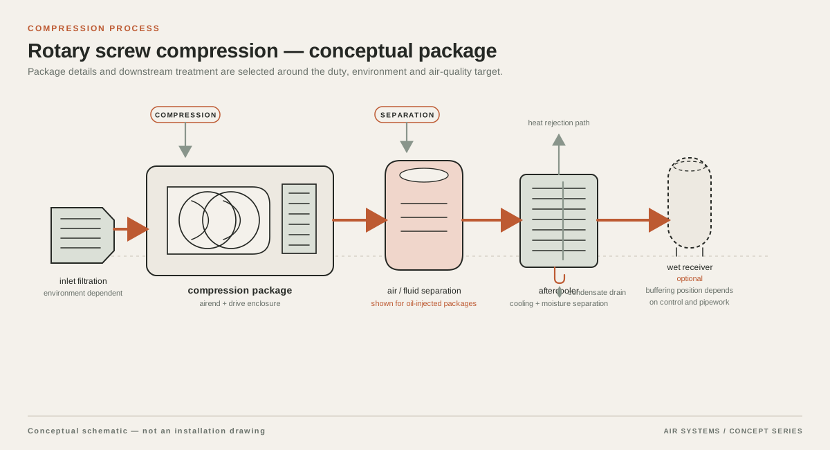
DETAILED SELECTION & OPERATION
Map each packaging duty before choosing a compressor
List every pneumatic consumer by machine and by operating state. Common duties include cylinder actuation, grippers, vacuum generation, air knives, blow-off nozzles, reject mechanisms, film or label handling, and pressure regulation at a sealing or filling station. The Compressed Air & Gas handbook identifies automatic packaging machinery uses such as sealing, locating work and actuation; use that as a reminder to map functions rather than treating the line as one undifferentiated load. source title
Separate continuous consumption from short events. A regulator or continuously open air knife can establish the running load, while a valve manifold or blow-off nozzle can create a brief peak. Record whether events occur simultaneously on one machine, across several machines, or only during a changeover. A compressor should be compared against the resulting demand profile and required delivered pressure, not selected from motor size or the packaging format alone.
- Continuous: air knives, purge flows, leaks and continuously enabled vacuum equipment.
- Cyclic: cylinders, clamps, pick-and-place devices, seal bars and reject mechanisms.
- Intermittent peak: blow-off, cleaning pulses, simultaneous valve banks and restart events.
- Quality-sensitive: air contacting product, primary packaging or an exposed process zone.
Use machine pressure and flow data, not a packaging rule of thumb
Ask the OEM or machine integrator for the minimum inlet pressure at the machine connection, the normal operating pressure, the maximum permitted pressure, and the flow basis used for its consumption figure. Confirm whether the value is free air delivery, standard or normalised flow, or another reference condition. A nominal plant header pressure is not the same as pressure at a valve or nozzle after filters, regulators, hoses and quick couplings.
Check the worst operating combination. A line may run acceptably when only one station cycles, then lose force when several stations index together. Compare the pressure at the farthest point of use during that event, including the planned pressure-drop allowance. Do not raise plant pressure automatically: higher pressure can increase leakage and blow-off consumption and may exceed the machine's permitted inlet pressure.
| Item | Why it matters | RFQ evidence to request |
|---|---|---|
| Required inlet pressure | Sets compressor, regulator and distribution design boundaries | Minimum, normal and maximum pressure at the machine inlet |
| Air consumption | Separates base load from event load | Units, reference conditions, duty cycle and simultaneous consumers |
| Peak sequence | Shows whether storage or control must cover a short deficit | Cycle time, starts per minute and overlapping stations |
| Point of use | Determines hose, filter, regulator and nozzle losses | Connection size, route length and allowable pressure drop |
Manage intermittent peaks with controls and local storage
A receiver can buffer a short demand event, reduce rapid compressor cycling and stabilise a machine inlet when the supply source cannot respond instantly. The U.S. Department of Energy compressed air sourcebook describes receivers as part of the supply-and-demand system and as storage for peak demand events. Improving Compressed Air System Performance Do not treat a receiver as a substitute for sustained compressor capacity: it will eventually recover at the rate of net surplus flow.
For packaging, consider a main receiver near the compressor and a secondary receiver near a high-cycle machine or peak consumer when the layout and risk assessment justify it. The supplier should calculate useful storage using the actual pressure range, flow reference and event duration. Ask for the recovery time and the pressure at the point of use, not only vessel volume. The receiver's pressure rating, relief protection, drain arrangement, inspection and installation must also meet the applicable local pressure-vessel rules.
- Use sequencing or controls where machine logic can prevent simultaneous nonessential events.
- Use a local receiver only after confirming volume, pressure range, contamination control and safe installation.
- Investigate leaks and permanently open blow-off before adding compressor capacity.
- Specify drain and condensate handling so stored air does not introduce liquid downstream.
Protect pressure at the packaging machine
Packaging machines are often sensitive to the pressure available at a regulator, valve island or nozzle. Size the main header and branch piping for the measured or quoted flow, route length and future connection, then check fittings, flexible hose, quick couplers, isolation valves and filters as a complete path. A small connection or clogged element can become the practical bottleneck even when the compressor outlet gauge looks normal.
Where several machines share a ring main, show which branches can operate together and where isolation is needed for maintenance. Put gauges or measurement points where a technician can compare header pressure with point-of-use pressure during a cycle. Keep condensate out of low points and provide service access. Any proposed pressure-drop value should state its flow condition and measurement location; do not accept an unqualified percentage as a system guarantee.
Match treatment to the packaging contact risk
Choose treatment from the contamination risk and the machine requirement, not from the word packaging alone. Refrigerated or desiccant drying, particulate filtration, coalescing filtration, activated-carbon treatment and point-of-use filtration address different contaminants and operating conditions. Confirm ambient temperature, inlet conditions, required pressure dew point, drain performance and the treatment pressure drop at the actual flow.
Classify each use as non-contact, incidental contact or direct contact with product, primary packaging or a controlled process zone. If air can contact exposed product or an internal package surface, obtain the customer's hygiene and contamination specification and require a documented validation plan. ISO's catalogue lists the ISO 8573 series for contaminant measurement and purity classes, including particle, humidity, oil aerosol, oil vapour, gaseous and viable microbiological measurements. ISO catalogue: compressed-air standards An oil-free compression process or a component certificate alone is not a blanket food-safety or assembly-approval claim.
Compare compressor configurations against the line profile
For a stable multi-shift base load, compare a fixed-speed arrangement with a variable-speed arrangement using the measured load profile, turndown behaviour, controls and lifecycle assumptions. For a line with modest average demand but sharp events, compare compressor response, receiver strategy and control sequencing rather than assuming variable speed alone solves the peak. Multiple smaller units may provide staging or resilience, but their combined control logic, minimum running load and maintenance isolation must be stated.
Packaging applications may use oil-injected or oil-free compression depending on required air quality, operating environment and total treatment design. Make the compression process, downstream treatment and point-of-use controls separate lines in the comparison. Request guaranteed values only under named test conditions and ask the supplier to identify what is standard, optional or excluded.
| Configuration question | Why packaging users should ask | Confirmation required |
|---|---|---|
| Single unit or staged units? | Affects redundancy, part-load behaviour and maintenance continuity | Control philosophy, minimum stable output and isolation plan |
| Fixed speed or variable speed? | Fit depends on load variation and operating hours | Performance curve at the quoted duty profile and test basis |
| Central or local receiver? | Changes peak response, recovery and pressure stability | Vessel rating, usable volume calculation and location |
| Treatment train | Quality and pressure drop depend on the complete train | Element grades, dew point, drains, monitoring and change-out basis |
RFQ checklist for a packaging compressed air system
An effective RFQ gives suppliers enough context to size the complete system without turning assumptions into promises. Attach the machine pneumatic schematic, OEM consumption data and a simple load schedule. State which values are measured and which are estimated. Ask for a marked-up P&ID, equipment schedule, pressure and flow reference conditions, treatment performance basis, utility requirements, commissioning tests and exclusions.
Require the quotation to identify standard versus optional configuration items. Ask how the proposal will demonstrate pressure at the farthest point during the defined peak sequence and how air quality will be verified at the relevant point of use. If the line has direct product or package contact, include the customer's documented quality limits and validation responsibilities rather than asking for a generic clean-air label.
- Machine make/model and pneumatic schematic, including all concurrent stations.
- Minimum, normal and maximum inlet pressure; flow units and reference temperature/pressure.
- Cycle time, starts per minute, changeover profile, shifts and future expansion allowance.
- Base load, peak flow, peak duration and acceptable pressure variation at each critical point.
- Air-contact classification, contaminant limits, dew point, filtration and monitoring requirements.
- Room conditions, electrical supply, noise limits, ventilation, condensate route and local codes.
- Receiver strategy, control sequence, redundancy expectation, commissioning tests and service scope.
SELECTION & OPERATION
Frequently asked questions
How much compressor capacity does a packaging machine need?
There is no reliable universal value. Add the machine builder's continuous and cyclic consumption using one stated flow reference, then test the worst simultaneous sequence and include distribution and treatment losses. A supplier should show the assumed duty cycle, point-of-use pressure and recovery requirement rather than sizing from machine size, package count or motor horsepower.
Do packaging lines always need a larger air receiver?
No. A receiver can buffer a short peak and improve control stability, but it cannot replace sustained compressor flow. Its useful volume depends on the permitted pressure swing, event duration, flow reference and recovery time. Ask for a calculation and confirm vessel compliance, drains and the receiver's location before treating added storage as the solution.
What air quality should be specified for packaging equipment?
Specify it by use. Non-contact actuators may have different requirements from air that contacts exposed product, primary packaging or a controlled process zone. Define particles, water, oil and any microbiological or gaseous contaminants using the applicable customer and regulatory basis, then validate at the point of use. Oil-free compression by itself is not a food-safety guarantee.
Can a blow-off nozzle be connected directly to the plant header?
Only after checking the nozzle's flow, duty cycle, pressure requirement and effect on other consumers. A short high-flow pulse may need local storage, a regulator, a suitable valve and a correctly sized branch. Measure pressure at the nozzle or machine connection during the event; the compressor outlet gauge alone cannot prove adequate performance.
Technical references
- Compressed Air & Gas ↗
Examples of compressed air use in automatic packaging machinery, including sealing, locating work and actuation.
- Improving Compressed Air System Performance ↗
System-level treatment, distribution, demand-side and receiver concepts, including storage for peak demand events.
- ISO catalogue: compressed-air standards ↗
The ISO 8573 series and related contaminant measurement topics for compressed air, including particles, humidity, oil aerosol, oil vapour, gases and viable microbiological contamination.