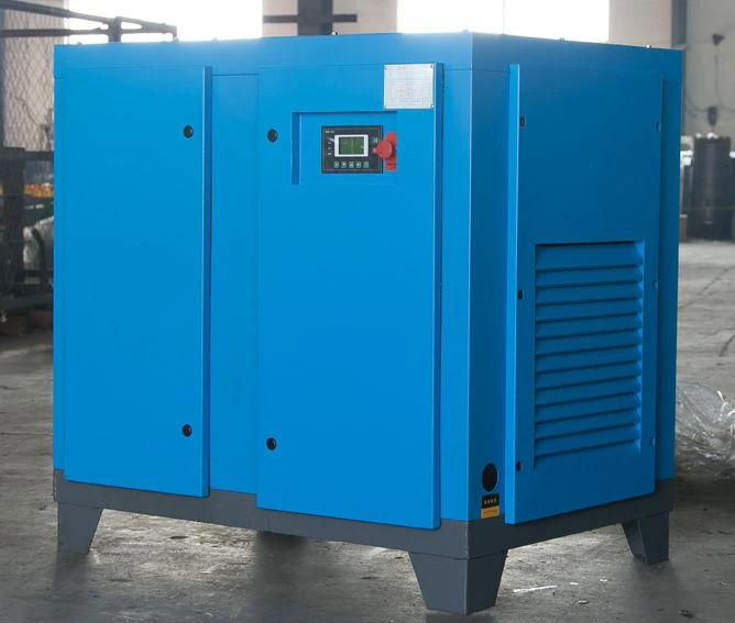
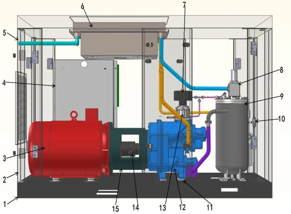
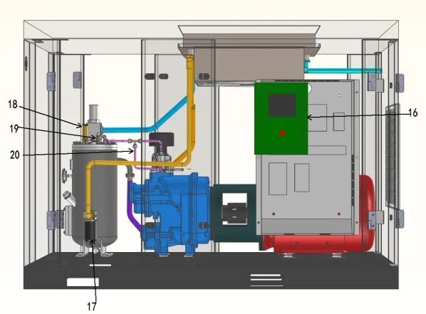
Complete compressed air system.
Combine compression, cooling, treatment, storage and distribution at the required pressure and point-of-use air quality. The layout below explains the system interfaces; it is not a photograph of an installed project.
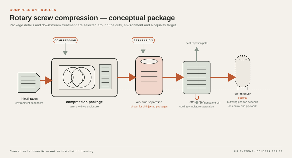
DETAILED SELECTION & OPERATION
How two-stage compression works
In a typical two-stage rotary screw arrangement, the first airend compresses atmospheric air to an intermediate pressure. The second airend receives that partially compressed air and raises it to the required discharge pressure. The stages are connected by an interstage path that may include cooling and separation equipment, depending on the technology and package design. This staged path is different from simply fitting a larger motor to a single-stage machine; the complete airend, cooling, control and protection design must be assessed together.
The exact pressure split between stages is a design choice, not a buyer specification to assume. It depends on the final pressure, airend geometry, inlet conditions, cooling method, lubricant or dry-running arrangement and the supplier's certified performance map. Ask for the stage arrangement and the conditions used for the quoted flow and power. The DOE compressed air sourcebook and CAGI selection material are useful background references, but neither establishes availability of a product on this site.
When to evaluate a two-stage machine
A two-stage screw compressor is worth comparing when the plant has a material continuous or long-duration air load, a defined discharge-pressure requirement, and enough operating data to compare package power at a common flow and pressure basis. The potential advantage should be assessed over the actual duty cycle, not inferred from the name alone. A high-load base-load machine and a short, intermittent peak load may need different combinations of compressor capacity, storage and controls.
- Good candidates for evaluation: sustained flow, a clearly defined pressure setpoint, measured load data and meaningful annual run hours.
- Reasons to pause: uncertain demand, excessive oversizing, difficult heat rejection, limited maintenance access or a process that cannot use the quoted flow.
- Do not choose solely from motor horsepower, a marketing efficiency claim or a nominal maximum pressure.
Configuration options to compare
Two-stage screw compressors can be offered in different configurations. The following are comparison items for an RFQ, not specifications offered by this website. A supplier should identify which items are standard for the proposed configuration and which are optional or unavailable for the requested duty. Lubricated and dry-running designs have different heat-management, air-quality and maintenance questions. An oil-injected design should be evaluated with its separator, filtration and downstream treatment rather than described as oil-free air.
| Comparison item | Why it matters | Supplier confirmation requested |
|---|---|---|
| Compression arrangement | Determines how the two airends, stage pressures and protection logic interact. | Stage type, pressure split, airend arrangement and applicable performance documentation. |
| Cooling path | Interstage and final cooling affect temperature control, condensate handling and room heat rejection. | Air- or water-cooled design, cooler duties, approach assumptions and condensate provisions. |
| Drive and control | Controls affect loading, unloading, sequencing and response to changing demand. | Fixed- or variable-speed arrangement, control range, motor/drive data and sequence logic. |
| Air quality and treatment | Compression technology does not by itself define point-of-use purity. | Lubricant approach, separator data, recommended filters/dryer and requested ISO 8573-1 test evidence. |
| Service arrangement | Two stages add components that need inspection and access. | Maintenance tasks, access clearances, parts strategy and intervals tied to OEM, ambient and duty. |
| Package integration | Receivers, dryers and distribution losses affect delivered pressure and usable flow. | Connection sizes, allowable pressure loss, receiver/interface requirements and controls integration. |
Cooling, condensate and air treatment
Compression raises air temperature. In a two-stage package, the interstage cooling path can remove heat before the second stage, while an aftercooler reduces discharge temperature and helps condense moisture for removal. The arrangement varies by technology, so request a process schematic that identifies the interstage cooler, aftercooler, separator, drains and any lubricant circuit. A cooler does not eliminate the need to manage condensate or to verify the temperature at the compressor outlet and dryer inlet.
Select downstream treatment from the required pressure dew point, particles, oil and other contaminants at the point of use. A dryer or filter creates its own pressure loss and maintenance requirements. If a process needs a defined ISO 8573-1 class, state the class and test method in the RFQ and request evidence for the complete delivered air path. A component certificate alone is not assembly approval, and an oil-free compression process is not a blanket food-safety or contamination guarantee.
Compare pressure, flow and package power consistently
Compare quotations only when pressure, flow reference, inlet conditions, discharge temperature and measurement boundary are aligned. Ask whether flow is stated as FAD, free-air delivery, or another normalized/standard volume basis; record the reference pressure and temperature. Confirm whether the quoted pressure is gauge or absolute and whether it is compressor discharge pressure or pressure available at the point of use. A nominal flow at a different basis can make two apparently similar offers incomparable.
Use measured demand where possible: minimum, average, peak, peak duration, shift pattern and future load. Then account for receiver storage, dryer and filter pressure loss, ring-main loss, elevation and required minimum pressure at critical users. Request package power at the same operating points as flow, including full-load, part-load and controlled transitions. Gardner Denver notes that package efficiency and system pressure drop depend on more than the airend; request the supplier's boundary conditions rather than assuming a saving.
Installation and system integration
Confirm the compressor-room layout before selecting a package. Provide ambient temperature range, altitude, humidity, ventilation concept, cooling-water conditions if applicable, allowable noise exposure, lifting route and service clearances. Heat rejected by the compressor and coolers must be handled by the room or a planned heat-recovery system. The supplier should state the required ventilation or cooling duty and the conditions behind any inlet or discharge temperature limits. Treat the receiver, dryer, filters and distribution main as part of the operating system, and confirm isolation, bypasses, drains, electrical protection, communications, emergency stop and sequencing.
Maintenance and lifecycle questions
A two-stage design adds inspection points such as two airends or compression paths, interstage cooling equipment, valves, sensors and control logic. Maintenance intervals depend on the OEM instructions, lubricant or dry-running design, ambient contamination, temperature, load profile and operating hours. Do not insert a universal service interval into a purchase specification. Request a task schedule, diagnostic method, spare-parts and warranty requirements, and compare electricity, cooling utilities, treatment consumables and downtime.
RFQ data to confirm before quotation
An effective RFQ gives suppliers the same operating basis and asks them to show what is included. Send a demand profile rather than only a target motor size. State whether the duty is base load, trim load, backup or a combination. Identify critical users, required air quality, start-up conditions and any expansion allowance. Ask each supplier to return a compliance schedule with deviations, assumptions and selectable alternatives.
Request written confirmation of the following items before technical evaluation:
- Required flow at minimum, normal and peak demand, with FAD or normalized-flow basis, reference temperature, reference pressure and humidity stated.
- Required pressure at the compressor outlet and at critical points of use, with gauge or absolute basis, allowable pressure drop and altitude identified.
- Two-stage technology, stage pressure split, airend arrangement, cooling method, aftercooler, separators, drains and expected outlet conditions.
- Quoted package power and sound data at the requested operating points, with measurement standard and package boundary identified.
- Lubricant approach, air-quality target, dryer and filtration train, ISO 8573-1 evidence offered, and any point-of-use validation required.
- Electrical supply, motor/drive data, controls protocol, sequencing requirements, installation clearances, ventilation or cooling-water duty and lifting constraints.
- Maintenance tasks and intervals tied to the proposed OEM configuration, ambient and duty; parts, warranty, commissioning and service response assumptions.
- Scope, exclusions, lead time, price validity, country of manufacture and availability, all subject to supplier confirmation rather than assumed by this page.
SELECTION & OPERATION
Frequently asked questions
Is a two-stage screw compressor always more efficient than a single-stage compressor?
No. Staged compression can reduce the work required in some operating ranges, but the result depends on pressure, flow, inlet conditions, cooling, controls, package losses and duty cycle. Compare supplier-certified package power at the same flow and pressure basis, including part-load behavior and treatment pressure loss.
Does two-stage mean the compressed air is oil-free?
No. Two-stage describes the compression arrangement, not the contamination class. A lubricated two-stage machine needs an appropriate separator and treatment train. If the process requires a specified ISO 8573-1 class, put the class, test conditions and evidence requirements in the RFQ and verify the complete air path.
What operating data should I provide when requesting a two-stage compressor quotation?
Provide minimum, average and peak flow; peak duration and shift pattern; required pressure at the compressor and points of use; flow and pressure reference bases; ambient and altitude; air-quality target; electrical supply; cooling conditions; installation constraints; and planned operating hours. A measured load study is preferable to selecting from motor horsepower alone.
Are maintenance intervals the same for every two-stage screw compressor?
No. Intervals depend on the specific OEM design, lubricant or dry-running arrangement, ambient contamination, temperature, loading and hours. Request the proposed model's maintenance schedule, service tasks, access requirements and parts recommendations as part of the quotation.
Technical references
- Improving Compressed Air System Performance (DOE Compressed Air Sourcebook) ↗
General compressed-air system engineering context, including staged rotary screw arrangements and the role of cooling and system equipment; source PDF text extraction was limited, so no numerical performance claim is taken from it.
- Rotary Selection Guide (Compressed Air and Gas Institute) ↗
Neutral rotary compressor selection and comparison context; use the supplier's applicable test data and stated reference conditions for any quotation.
- Working Principle of a Rotary Screw Air Compressor (Gardner Denver) ↗
Explanation that two-stage lubricated rotary compressors compress in two steps, and that added stages bring additional components and complexity; also supports package-level efficiency and pressure-drop comparison considerations.