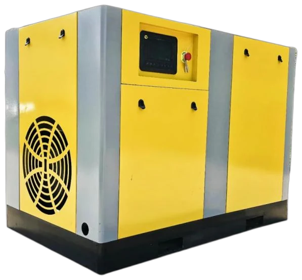
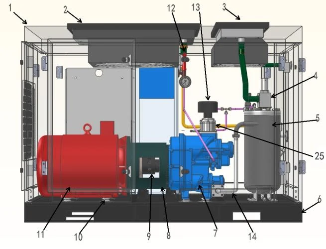
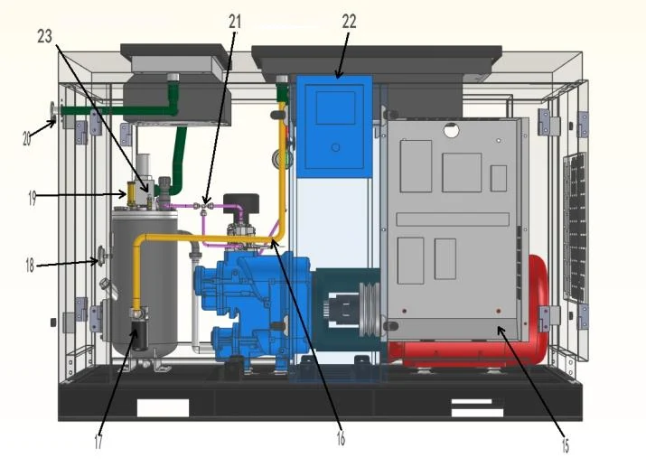
Complete compressed air system.
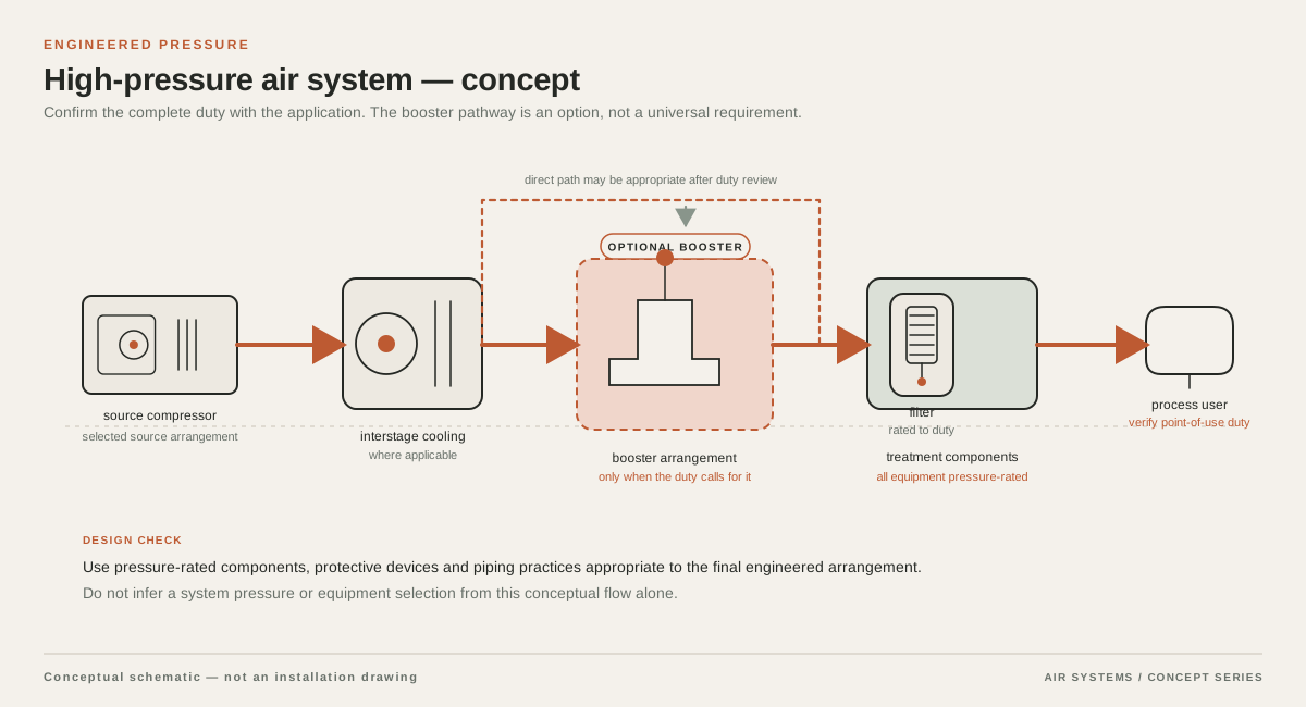
Combine compression, cooling, treatment, storage and distribution at the required pressure and point-of-use air quality. The layout below explains the system interfaces; it is not a photograph of an installed project.
DETAILED SELECTION & OPERATION
When high-pressure compression is appropriate
High pressure is justified when a process specification requires it at a defined connection, such as a pressure vessel filling step, a pressure test, a specialist actuator, a gas-assist process or another machine with an OEM pressure requirement. Start with the equipment documentation and the pressure actually needed during the event. A nameplate maximum is not the same as operating pressure, and a downstream regulator cannot create flow that the compressor, receiver and piping cannot supply.
The first design question is whether the whole system needs high pressure or only a branch. A dedicated package, booster or local receiver can sometimes serve a peak user while the general plant remains at a lower pressure. The appropriate arrangement depends on duty hours, peak duration, permitted pressure variation and existing compressor capability. A supplier should compare these configurations rather than assume that one high-pressure compressor must feed every load.
High pressure is not a substitute for finding restrictions, undersized pipe, dirty filters, leaks or an incorrectly set control valve. State whether the requested value is gauge or absolute pressure, and identify the minimum pressure the process must see while consuming air.
- Define the minimum pressure at the actual point of use, not only the compressor outlet setpoint.
- Separate continuous base demand from short high-pressure peaks.
- Check whether a booster, local storage or a dedicated branch can avoid pressurizing unrelated loads.
- Treat 20, 30 and 40 bar as buyer requirement categories, not as proof that this site supplies equipment at those ratings.
Pressure, flow and reference conditions must be stated together
A high-pressure RFQ is incomplete if it states only bar. Request the required flow in a named unit and reference basis, such as FAD or another explicitly defined mass or volume basis. Ask the supplier to state the inlet temperature, inlet pressure, humidity assumption and discharge reference used for the quoted flow. A value in m³/min at one condition cannot be compared directly with a value in m³/min at another condition without the bases being reconciled.
Describe both steady and transient demand. Include normal flow, maximum flow, minimum turndown, start-up demand, peak duration, repetitions per hour and the allowable pressure dip. If the compressor feeds storage before a fast event, provide the usable receiver pressure range and the recovery time required between events. If a machine consumes air only intermittently, a time-averaged figure may conceal the peak that controls package selection.
Ask for pressure at the compressor discharge, after treatment, at the receiver and at the process connection. These are different locations. The quoted compressor pressure must cover treatment, valves, pipe and elevation losses while still meeting the process minimum. Do not accept a flow comparison that omits the discharge pressure or changes the reference temperature between alternatives.
| RFQ item | What to state | Why it changes selection |
|---|---|---|
| Pressure | Minimum and normal pressure at point of use; gauge or absolute basis | Determines compression ratio, controls, treatment rating and pressure-drop allowance |
| Flow | Continuous, peak and event duration with named reference conditions | Separates base capacity from receiver-supported transient demand |
| Duty | Hours per day, days per week, starts, ambient range and load pattern | Affects cooling, motor, control strategy and maintenance planning |
| Quality | Required particle, water, oil and any special contaminant limits | Determines filtration, drying, monitoring and validation scope |
| Installation | Indoor or outdoor location, utilities, noise, ventilation and access | Controls package layout, cooling and service feasibility |
Compare staged compression, boosters and dedicated packages
A high-pressure system may use a compressor designed for the final pressure, a lower-pressure compressor feeding a booster, or multiple stages within a package. Staging is not a universal performance promise. It changes the compression path, intercooling or aftercooling needs, control arrangement, oil-management approach and maintenance access. The DOE compressed-air sourcebook notes that multiple stages can be used to achieve higher pressures or improve efficiency at a given pressure, but the actual result depends on the selected technology and operating point Improving Compressed Air System Performance.
A booster can be attractive when an existing plant compressor already supplies suitable inlet pressure and the high-pressure demand is localized or intermittent. It can be a poor fit when the base compressor is undersized, inlet pressure varies, or the booster must run for long periods at a duty beyond its intended application. Request the complete pressure ratio, inlet pressure range, outlet pressure control range, flow at each condition and any minimum inlet-flow or cooling requirements.
A dedicated high-pressure package may simplify ownership when the demand is continuous and independent, but it still needs an engineered interface with storage and treatment. Ask suppliers to identify which items are included, which are optional, and which must be provided by others. Confirm the proposed motor, stage count, control panel, cooler and enclosure in the quotation.
- Compare final-pressure compressor, booster-fed arrangement and multi-stage package on the same inlet and outlet reference conditions.
- Ask for stage-specific cooling, condensate management and protection details.
- Confirm whether the proposed unit is intended for continuous, cyclic or emergency duty.
- Do not infer energy performance from the words two-stage, booster or high pressure alone.
Treatment must be selected for the high-pressure duty
Compression changes the temperature, water load and contaminant-management problem. High-pressure air commonly needs an aftercooler, condensate separation, filtration and drying arrangement selected for the actual pressure and flow. Treatment pressure ratings, allowable differential pressure, drain behavior and service access must be checked as a complete chain. A filter or dryer that is acceptable at one pressure and flow may not be appropriate at another, and any pressure drop must be included in the compressor discharge requirement.
Define the end-use quality requirement rather than asking for clean air as a general label. ISO 8573-1:2010 specifies compressed-air purity classes for particles, water and oil, independent of where in the system the air is specified or measured, and it also identifies gaseous and microbiological contaminants ISO 8573-1:2010. Select the required class and measurement method with the process owner. Oil-free compression does not by itself establish the purity of the delivered assembly, and a component certificate is not assembly approval.
For breathing air, food contact, pharmaceutical, electronics or other sensitive duties, obtain the applicable legal, customer and validation requirements before choosing equipment. Request a proposed treatment schematic, sampling points, alarm strategy, drain handling and evidence plan. Any claim about purity must identify the test method, operating condition, sampling location and responsibility for validation.
Receivers, cooling and pipework are part of the package
A receiver can buffer a short high-pressure event, reduce rapid cycling and provide a defined place for condensate separation, but it does not replace compressor capacity for a sustained load. Its useful contribution depends on the usable pressure band, event flow and duration. Request the calculation assumptions, receiver design pressure, relief protection, drain arrangement, inspection access and jurisdiction-specific registration or inspection requirements. Do not select a vessel from nominal volume alone.
Cooling deserves special attention because compression and high-pressure discharge can produce substantial heat. Ask how inlet temperature, ambient temperature, cooling medium, ventilation and fouling allowance affect the proposed operating envelope. Confirm the location and temperature of the air delivered to the next component, as well as the handling of condensate and any oil-bearing waste. Maintenance intervals depend on OEM instructions, ambient conditions and actual duty; no universal interval should be assumed.
Pipework and fittings must be rated for the branch pressure and temperature, not merely the lower-pressure plant header. Check peak-flow pressure drop, isolation and non-return devices, relief discharge routing, vibration, supports and inspection access.
Controls and installation need a high-pressure safety review
Specify the control objective in process terms: stable point-of-use pressure, receiver recovery, sequencing with a base compressor, or a controlled filling cycle. Request setpoint limits, ramp behavior, restart logic, high-temperature and high-pressure trips, alarm contacts, emergency isolation and communications requirements. If the proposed arrangement includes a booster, confirm how it responds to low inlet pressure and whether a failure can expose downstream equipment to an unacceptable condition.
High-pressure receivers, coolers, valves and piping may be subject to local pressure-equipment rules, inspection regimes and relief-device requirements. The responsible engineer must identify the governing jurisdiction and confirm design, testing, marking and commissioning evidence. Electrical classification, ventilation, noise, lifting, access and discharge routing also belong in the installation review. Separate included safety devices from items requiring site engineering or third-party approval.
What to include in a high-pressure compressor RFQ
Send suppliers a process data sheet rather than a one-line request for a high-pressure compressor. Include the required pressure category, exact pressure basis, flow reference, operating profile, inlet conditions, air quality, location, utilities, ambient range, noise limit and delivery boundary. Include a simple schematic showing the existing compressor, proposed booster or high-pressure package, receiver, treatment, point of use and relief discharge. Mark which values are measured and which are design targets.
Ask each bidder to return a marked-up process and instrumentation diagram, equipment list, utility schedule, pressure-drop statement and assumptions register. Require separate identification of base, optional and third-party items. Request guaranteed values only where the supplier is willing to state the test standard, reference conditions, tolerance and remedy. Otherwise label the value as an estimate or selection basis. This prevents a nominal pressure rating from being mistaken for delivered performance.
Use lifecycle comparison, not a lowest-purchase-price ranking. Compare quoted input power at the requested pressure and flow, control behavior, treatment consumables, condensate handling, service access, expected spares, commissioning tests and the impact of downtime. Availability, model identity, certifications, pricing and delivery are not verified by this page and must be obtained directly from the responding supplier.
| Ask the supplier to return | Minimum clarification |
|---|---|
| Performance basis | Flow unit and reference conditions, pressure measurement point, inlet range and tolerances |
| Configuration | Compressor or booster architecture, included stages, cooler, receiver, treatment and controls |
| System interface | P&ID, connection sizes and ratings, pressure drop, relief path and electrical load |
| Operating envelope | Ambient limits, duty cycle, turndown, restart behavior, alarms and trip conditions |
| Evidence and service | Test method, commissioning checks, maintenance assumptions, spares and exclusions |
Data to confirm before any recommendation
Before a supplier recommendation can be evaluated, confirm the process OEM requirement and the actual pressure at the point of use during the highest-demand event. Confirm whether the application needs continuous high pressure or only a short burst, whether existing compressed air can feed a booster, and whether storage is allowed. Record measured flow and pressure where possible instead of relying on motor size, pipe size or a historical compressor nameplate.
Also confirm pressure-vessel and electrical requirements, treatment quality class, sampling responsibility, ambient conditions, cooling or ventilation, noise, maintenance access and delivery boundary. Request the proposed model, performance schedule, stock, price, delivery terms and supporting documents in the RFQ.
- Process equipment OEM pressure and flow requirement at the connection.
- Gauge versus absolute pressure and flow reference temperature, pressure and humidity.
- Peak event duration, repetition rate, receiver pressure band and recovery target.
- Existing compressor inlet pressure and suitability for a booster arrangement.
- Required ISO 8573-1 purity class or other process-specific quality evidence.
- Jurisdiction, vessel inspection, relief protection, electrical supply and installation conditions.
SELECTION & OPERATION
Frequently asked questions
Does a higher pressure rating mean the compressor will deliver the required flow at that pressure?
No. A pressure rating or category does not establish delivered flow, operating duty, reference conditions or pressure at the point of use. Request a supplier curve or stated performance basis at the required pressure, inlet condition and flow, then account for treatment, piping and storage losses.
Should I raise the whole plant header for one high-pressure machine?
Usually that should be evaluated rather than assumed. A dedicated branch, booster or local receiver may isolate the high-pressure demand, but the best choice depends on peak duration, existing compressor inlet pressure, allowable pressure variation, flow and installation rules. Compare complete system concepts with the supplier.
Can a receiver replace a high-pressure compressor sized for the peak flow?
A receiver can buffer a defined short event, but it cannot supply sustained demand without recovery. The supplier should show the usable pressure range, event duration, repetition rate, recovery time and assumptions used to size the compressor and vessel.
Does oil-free compression automatically meet a high-purity requirement?
No. Compression technology is only one part of delivered air quality. Specify the required particle, water and oil classes or other contaminant limits, then select treatment, monitoring and validation evidence for the complete assembly and point of use.
Technical references
- Improving Compressed Air System Performance ↗
DOE compressed-air guidance on system-level performance and the use of multiple stages to achieve higher pressures or improve efficiency at a given pressure.
- How to Select an Air Compressor ↗
CAGI guidance that compressor selection should consider the complete air system and ownership cost, including power cost, rather than purchase price alone.
- ISO 8573-1:2010 — Compressed air — Part 1 ↗
The official ISO abstract defining purity classes for particles, water and oil, independent of the location where air is specified or measured, and identifying gaseous and microbiological contaminants.