INDUSTRIAL COMPRESSOR EQUIPMENT

30 Bar Air Compressors

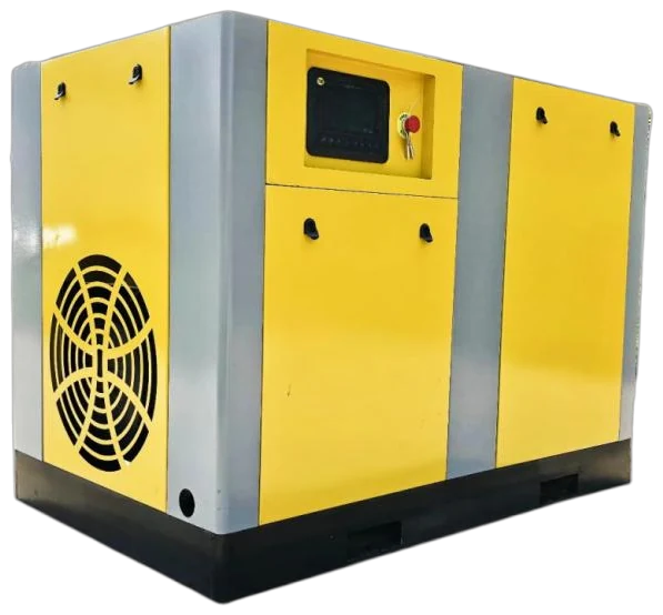
Specify a 30 bar (3.0 MPa) compressed-air package around the pressure and nominal volume flow required at the point of use. Review the documented EBLW, EBLGII and EBLGIII 3.0 MPa catalogue configurations, then define compression arrangement, aftercooling, pressure-rated treatment and receiver storage together. The photographs show the electric high-pressure series only; they do not identify a particular model. Send the machine specification, duty cycle, site conditions and air-quality target for a matched quotation.

  • 30 bar (3.0 MPa) catalogue reference configurations
  • Source nominal volume flow retained without calling it FAD
  • Cooling, treatment and receiver scope rated for the working pressure
  • Pressure and flow defined at the point of use
01

30 bar catalogue configurations for initial comparison

The 30 bar (3.0 MPa) selection table lists documented electric medium/high-pressure examples from the EBLW, EBLGII and EBLGIII model families. Its validated entries span source nominal volume-flow values from 1 to 33 m³/min, so the table can help frame a small process branch as well as a larger high-pressure utility duty. It is a starting configuration list: select on the pressure and flow required at the use point, then define the package boundary around it.

The source labels flow as nominal volume flow in m³/min. It does not identify those values as FAD, so do not compare them with another bidder’s FAD, standard-flow or normal-flow figure without first aligning reference conditions. Likewise, motor rated power is one catalogue field, not the electrical-input figure for a finished compressor, cooler, dryer, receiver and control package.

  • Use 30 bar (3.0 MPa) as the declared system pressure category and state the required pressure at the measurement point.
  • State nominal, continuous, peak and recovery requirements separately, with one declared flow reference basis.
  • Ask for the selected configuration’s delivered-flow evidence at the stated pressure and operating conditions.
  • Define the included compressor, cooling, treatment, storage, controls and distribution interfaces before comparing quotations.

EQUIPMENT CONFIGURATIONS

Compare the series specifications.

Compare the listed pressure and flow basis, then send the application and operating profile for a matched quotation.

30 bar (3.0 MPa) electric medium/high-pressure catalogue configurations
Catalogue modelMotor rated power (kW)Nominal volume flow (m³/min)Discharge pressure
EBLW-1/30-15Kw15130 bar (3.0 MPa)
EBLW-2/30-30Kw30230 bar (3.0 MPa)
EBLW-3/30-37Kw37330 bar (3.0 MPa)
EBLGII-3.5/30-45Kw453.530 bar (3.0 MPa)
EBLGII-5/30-55Kw55530 bar (3.0 MPa)
EBLGII-8/30-75Kw75830 bar (3.0 MPa)
EBLGII-10/30-110Kw1101030 bar (3.0 MPa)
EBLGII-12/30-132Kw1321230 bar (3.0 MPa)
EBLGII-16/30-185Kw1851630 bar (3.0 MPa)
EBLGII-20/30-200Kw2002030 bar (3.0 MPa)
EBLGIII-24/30-250Kw2502430 bar (3.0 MPa)
EBLGII-28/30-315Kw3152830 bar (3.0 MPa)
EBLGII-33/30-355Kw3553330 bar (3.0 MPa)

Catalogue basis: flow is nominal volume flow (m³/min), not identified as FAD; motor rated power is not package electrical input. Final duty and system scope are defined in the quotation.

Source: Dezhou YITong electric medium/high-pressure selection catalogue (supplied PDF: 电动中高压选型手册-.pdf) · pp. 5, 6, 7, 8. Final model duty and supply scope are stated in the quotation.

02

Choose direct high-pressure compression or a booster path

A direct 30 bar package is a practical comparison where a high-pressure duty is sustained, coordinated across several users or supplied through a dedicated header. Where only one local machine has an intermittent 30 bar event, compare a lower-pressure base system plus booster as a separate architecture. The better option depends on the event profile, inlet pressure stability, allowed recovery time, location of storage and how the high-pressure user is isolated when idle.

Compare complete system boundaries rather than an unsupported efficiency claim. A meaningful proposal states the assumed operating hours, pressure at the compressor and process connection, flow reference, control method, auxiliary loads and treatment pressure loss. It should also explain how the high-pressure branch responds when its user starts, stops or is offline.

30 bar configuration questions to include in the RFQ
Comparison itemDirect 30 bar packageLower-pressure base system plus booster
Best fit to assessSustained or shared 30 bar demand.A local or intermittent 30 bar duty.
Compression scopeState compressor arrangement, cooling and high-pressure control sequence.State base-air capacity, booster inlet-pressure range and booster discharge conditions.
Storage and treatmentRate receiver, dryer, filters, drains and fittings for the 30 bar duty.Identify storage on both sides of the booster and the pressure rating of each treatment stage.
Evidence to requestDeclared flow at specified pressure, reference conditions and test boundary.Booster inlet conditions, discharge flow, event recovery assumptions and control sequence.

COMPONENT ARRANGEMENT

Package components.

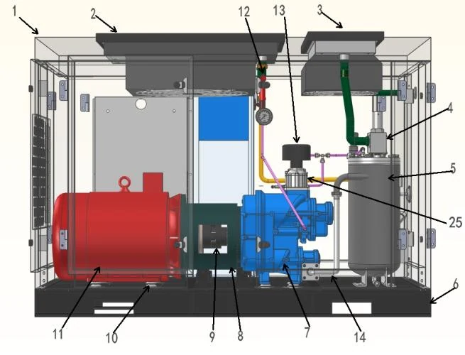
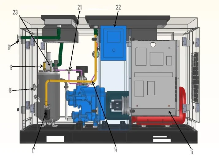
Catalogue structure diagrams show the arrangement of compression, controls and cooling. Check clearances and installation scope for your chosen configuration.

High-pressure compressor catalogue structure diagram showing motor, compression unit and piping.
Product structure diagramCatalogue structure diagram. Confirm the selected package layout.
High-pressure compressor catalogue diagram showing controls, oil filter and piping layout.
Product structure diagramCatalogue structure diagram. Confirm the selected package layout.
03

Build a 30 bar package around cooling, treatment and storage

For the source table’s 3.0 MPa entries, the temperature fields show ≤90°C without a separate aftercooler and ≤ambient +18°C with a separate aftercooler. Use those catalogue fields only as a starting point for the proposed cooling arrangement. The quotation must identify cooling medium, design ambient or cooling-water conditions, drain locations, discharge temperature at the stated boundary and the pressure rating of the complete air path.

Aftercoolers, moisture separators, automatic drains, filters, dryers, receivers, regulators, hoses, valves and gauges all need a working-pressure and temperature rating suitable for the 30 bar system. State the required air quality at the process point and leave the treatment pressure drop in the pressure budget. A receiver can buffer an event and let the compressor or booster recover between events, but it must be sized for the usable pressure band, rated for the jurisdiction and equipped with the required relief, isolation, inspection and drain provisions.

04

Use 30 bar only where the process requirement supports it

A 30 bar system should be considered when the machine manufacturer or process specification calls for approximately 3.0 MPa at the relevant point of use. High-pressure forming or blowing duties can have short, high-flow events; a test or process branch may instead have a steadier demand. In either case, record the actual pressure, flow, event duration, overlap with other users and allowed recovery time before choosing a direct package, booster path or receiver location. For process-specific context, see PET bottle blowing and laser cutting.

The supplied catalogue identifies this high-pressure family as a micro-oil screw series, not as an oil-free range. It must not be represented as automatically suitable for every PET, food-packaging or direct-product-contact duty. Define the required particles, water, oil and any process-specific contaminants at the sampling point; then assess compression technology, treatment, drainage, pipework and verification together. ISO 8573-1 provides the framework for stating particles, water and oil classes, but a class specification does not by itself prove a finished system is suitable for a particular process.

05

Protect the pressure boundary during installation and service

Define electrical supply, starting or drive arrangement, heat rejection, ventilation, condensate handling, acoustic limit, lifting route, foundations and service clearance before finalising the package. Keep access to coolers, filters, drains, relief devices, gauges and isolation points clear. High-pressure branches should have a documented pressure boundary from compressor discharge to use point, including the receiver, flexible connections and any booster or regulator.

Controls must be checked against the real event profile. Request pressure sequencing, high-temperature protection, alarm and trip set points, restart behaviour, remote signals and the logic for a booster or receiver branch. Maintenance should follow the offered OEM configuration and local safety procedure, covering lubricant, filters, coolers, drains, relief devices and pressure isolation. Acceptance testing should identify pressure measurement points, the flow basis, stabilization period, permitted tolerance, electrical measurement boundary and any air-quality sampling method.

Complete compressed air system.

Combine compression, cooling, treatment, storage and distribution at the required pressure and point-of-use air quality. The layout below explains the system interfaces; it is not a photograph of an installed project.
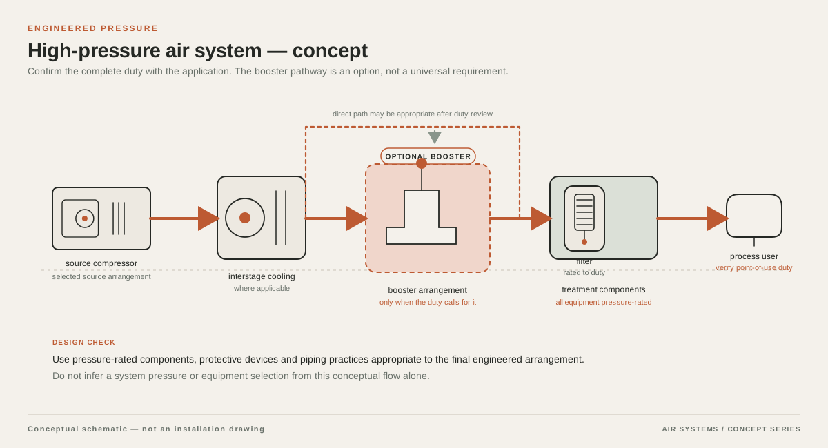
Conceptual supply arrangement for 30 Bar Air Compressors
System schematic. Component sequence depends on the selected equipment and duty.

DETAILED SELECTION & OPERATION

06

Match the compression arrangement to the 30 bar duty

The supplied medium/high-pressure catalogue describes its 1, 2 and 3 m³/min machines as twin-screw-plus-scroll arrangements. For the 4–6 m³/min range, it describes either a small-displacement parallel arrangement or a combination of twin-screw and single-screw compression; it also describes a two-stage twin-screw-plus-scroll arrangement for models above 23 m³/min. The same source describes conventional machines as using single-screw or twin-screw structures. These are family-level construction descriptions, rather than a model-by-model assembly declaration.

The 30 bar table spans those size bands, so the RFQ should name the selected catalogue model and ask for the exact compression train, stages, interstage cooling arrangement and lubrication path. The supplier’s series diagrams identify compression equipment, motor, oil/air separation, oil cooling, a separate air-cooler position, controls and safety devices; they should be read as a series arrangement diagram, not as proof of an identical layout on every model.

07

Illustrative 30 bar branch-sizing check

This is a teaching example, not plant data or a model recommendation. Assume a 30 bar process event requires 1.8 m³/min for 20 minutes in each hour and a separate ancillary demand requires 0.2 m³/min continuously. All values are assumed to use the same nominal-volume-flow reference. The event contributes 1.8 × 20 ÷ 60 = 0.6 m³/min on a time-average basis. Adding the continuous ancillary demand gives a time-average requirement of 0.8 m³/min; when both occur together, the instantaneous branch requirement is 2.0 m³/min.

The 0.8 m³/min average does not determine compressor selection, and the 2.0 m³/min overlap is not a final capacity requirement by itself. Check the allowed pressure band, usable receiver volume, compressor or booster control response, recovery time, treatment pressure loss and demand growth. Do not choose a motor rating or catalogue model from this example. Use the pressure-selection guide, flow-basis guide and RFQ checklist to document the missing project inputs.

Teaching assumptions for one 30 bar branch
ItemTeaching assumptionCalculation result
Process event1.8 m³/min for 20 minutes per hour.Time-average contribution: 1.8 × 20 ÷ 60 = 0.6 m³/min.
Ancillary demand0.2 m³/min continuously.Time-average contribution: 0.2 m³/min.
Time-average branch demandBoth assumptions use one stated nominal-volume-flow basis.0.6 + 0.2 = 0.8 m³/min.
Simultaneous event demandProcess event and ancillary demand occur together.1.8 + 0.2 = 2.0 m³/min.

SELECTION & OPERATION

Frequently asked questions

Which documented configurations are listed for a 30 bar requirement?

The accompanying table lists validated 3.0 MPa catalogue examples from EBLW, EBLGII and EBLGIII families, with source nominal-volume-flow values from 1 to 33 m³/min. Use it to shortlist a configuration, then define the actual point-of-use pressure, flow basis, duty profile, cooling and treatment boundary in the RFQ.

Does this page use 30 bar and 3.0 MPa as the same pressure category?

Yes. This page presents the specified category as 30 bar (3.0 MPa). The source catalogue’s listed model codes use /30 and the corresponding pressure cells show 3. State whether the project pressure is gauge or absolute and identify the measurement point, because that project requirement is separate from the category label.

Are the listed m³/min values FAD?

No FAD designation is given in the source table. The table preserves the source term, nominal volume flow (m³/min). For a quotation comparison, ask each bidder to state whether its figure is FAD, inlet volume, standard flow or another basis, along with the reference conditions.

Can a 30 bar micro-oil screw package be used for every PET or food-packaging project?

No. The source family is identified as micro-oil screw equipment, not an oil-free range. PET and food-packaging duties must be assessed against the actual air-contact risk, process and machine requirements, air-quality target, treatment train, drainage and point-of-use verification. A pressure label or filter list alone does not establish suitability.

What should be included in a 30 bar compressor RFQ?

Provide the minimum and maximum pressure at the stated measurement point; nominal, peak and event flow with a declared reference basis; operating schedule and recovery time; selected direct or booster architecture; air-quality target; treatment and receiver scope; site ambient, altitude, utilities and electrical supply; and the local pressure-vessel, installation and acceptance-test requirements.

Technical references

  1. Improving Compressed Air System Performance: A Sourcebook for Industry ↗

    Qualitative guidance on system pressure, storage, distribution, controls and the need to assess a complete compressed-air system rather than compressor nameplate data alone.

  2. CAGI Electrical Handbook, Chapter 8: General Reference Data ↗

    The need to state barometric and absolute-pressure bases when comparing air-flow and intake calculations.

  3. ISO 8573-1:2010 Compressed air — Part 1 ↗

    The framework for specifying compressed-air particles, water and oil quality independently at a stated measurement location.

PROJECT QUOTATION

Specify your air system.

Send the working pressure, air demand and operating conditions. We will help select equipment and system components for your process.

Send your project requirements ↗