Complete compressed air system.
Combine compression, cooling, treatment, storage and distribution at the required pressure and point-of-use air quality. The layout below explains the system interfaces; it is not a photograph of an installed project.
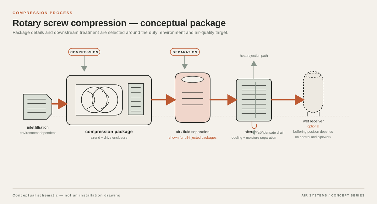
DETAILED SELECTION & OPERATION
Map the textile air load before selecting equipment
Separate the plant into process groups. An air-jet loom uses air at the weaving point to carry the weft yarn, while spinning, winding and other textile machines may use air for cleaning, yarn handling, clamping, motion control or actuators. Those duties should not be combined into one unexamined average. Ask each machine OEM for required inlet pressure, consumption basis, connection size, acceptable pressure fluctuation and whether the stated consumption is continuous, cyclic or a maximum.
Build a time-based demand profile for each production state: start-up, normal running, style change, cleaning, shift change and simultaneous operation of the largest number of machines. Record installed and future looms separately. A short peak from valves or blow-off can affect storage and header design even when its daily air volume is modest. A stable spinning load can affect compressor control selection in a different way. The resulting profile becomes the engineering comparison basis.
- List machines by process, quantity, OEM model and production speed.
- Record measured flow and pressure at the machine inlet where practical, not only at the compressor outlet.
- Mark intermittent blow-off, cleaning and pneumatic motion separately from process air.
- Include planned capacity, operating shifts and the consequence of a pressure dip on fabric or yarn quality.
Treat air-jet weaving and spinning as different duties
Air-jet weaving deserves its own calculation. The loom OEM may define nozzle arrangement, insertion speed, relay-jet behavior, allowed pressure band and consumption at a particular fabric style. Wider fabric, higher speed or a different yarn can change the requirement. Do not apply a universal bar or flow figure to every loom, and do not size the compressor from loom count alone. A quote should show how the supplier translated the OEM data into required free air delivery, receiver volume and distribution capacity.
Spinning and winding equipment should be assessed independently. Some machines may use air for suction, yarn handling or cleaning, while others use pneumatic actuators and controls. Their duty can be continuous, pulsed or sensitive to contamination and moisture. Ask whether air is discharged near product, yarn, sensors or bearings, and define any point-of-use filter or dryer requirement. Air used for housekeeping blow-off should be challenged and controlled rather than allowed to dictate the entire production system.
| Duty group | What to obtain from the plant or OEM | Selection implication |
|---|---|---|
| Air-jet weaving | Loom model, style, width, speed, nozzle data, inlet pressure and consumption basis | Assess fast demand changes, header stability, storage and machine-side pressure |
| Spinning and winding | Machine quantity, yarn/process, continuous or cyclic consumption, controls and cleaning duty | Compare base load with pulses and isolate unnecessary open blowing |
| Pneumatic equipment | Valve/actuator cycle rates, peak flow, operating pressure and simultaneous cycles | Check compressor controls, receiver response and local restrictions |
| Plant services | Maintenance air, conveying, instruments and shifts | Keep support loads visible instead of hiding them in a single allowance |
Make pressure and flow data comparable
A textile RFQ should state whether flow is FAD, actual volumetric flow, standard flow or another normalized basis. State the reference pressure, temperature, humidity convention and whether pressure is gauge or absolute. Do not compare a loom consumption number in normal cubic metres per minute with a compressor number in inlet cubic metres per minute without reconciling the bases. The same discipline applies to pressure: identify the required pressure at the machine inlet, then allow for treatment, piping, valves, filters and elevation only after those losses are calculated.
Pressure at the compressor discharge is not the same as pressure at a loom. Overspecifying plant pressure to cover an unknown distribution loss can increase demand and still fail to correct a restricted filter, small branch or undersized header. Request a pressure-drop schedule from compressor discharge through dryer, filters, receiver, ring main, branch and point-of-use connection. Require the supplier to identify assumptions and test points rather than silently adding an unexplained margin.
Compare compressor configurations against the load profile
The suitable compression arrangement depends on the base load, modulation range, number of machines, redundancy requirement, electrical supply and room conditions. A fixed-speed arrangement may be considered where a steady base load is well established; a variable-speed arrangement may be considered where demand varies materially. Neither label proves lower operating cost for a particular textile plant. Ask for part-load data on the proposed control range, sequencing logic, turndown behavior, restart constraints and the operating assumptions behind any energy estimate.
For a plant with many looms, compare a central station with appropriately zoned distribution and local storage. A smaller satellite package may be useful for a remote process or resilience objective, but it adds interfaces, maintenance points and treatment decisions. Specify whether a standby unit is intended for the whole plant, a critical loom group or safe shutdown only. Require the quotation to identify what is standard versus optional and to state all supplier-confirmed limits.
Match treatment and cooling to textile process risk
Compressed air treatment is part of the textile process specification, not an accessory selected after the compressor. Define acceptable particles, water and oil at each relevant point of use. ISO 8573-1 describes compressed-air purity classes for particles, water and oil and also identifies gaseous and microbiological contaminants; the applicable class must therefore be selected for the actual machine and process, then verified with suitable measurement. A filter element certificate alone does not establish the purity of the complete installed assembly at the loom.
Choose dryer type from the required pressure dew point, ambient conditions, downstream temperature, installation location and maintenance plan. Check condensate management, drain reliability and filter differential pressure. Textile rooms can be warm and dusty, so compressor intake location, ventilation, aftercooling and separation of hot exhaust from fresh intake air should be included in the layout review. Ask how the supplier will protect the stated performance when ambient temperature, shift pattern and filter loading differ from the quotation assumptions.
Use storage and distribution to protect loom pressure
Receivers can buffer short demand changes, reduce rapid compressor cycling and separate supply response from a fluctuating textile header. They do not create sustained air capacity. Locate and size storage from the measured peak, allowable pressure swing, compressor control behavior and local vessel rules. Where a loom group creates a sharp pulse, evaluate a local receiver or appropriately sized branch instead of increasing the entire plant pressure. Any receiver proposal must state volume, design pressure, relief protection, drains and inspection obligations subject to the applicable jurisdiction.
A ring main can improve resilience and reduce the effect of a single branch outage, but its benefit depends on pipe sizing, isolation points, slope, drains and actual flow direction. Keep process-critical loom branches distinct from maintenance air and high-consumption blow-off. At point of use, specify isolation, regulator, gauge, drain and filtration where needed. Measure pressure at representative machines during the worst credible production combination; a compressor-room gauge alone cannot demonstrate stable loom pressure.
Plan maintenance around textile operating conditions
Maintenance intervals depend on the selected OEM, ambient dust, intake conditions, operating hours, duty cycle and treatment arrangement. The RFQ should require an OEM maintenance schedule and list of consumables rather than assuming a universal interval. Include intake filters, compressor service items, dryer checks, automatic drains, receiver inspection, safety devices, filter elements and condensate handling. Make access, lifting and lockout requirements visible in the room layout.
Verification should use the same definitions as the design. Record pressure and flow at the compressor, main header and selected loom groups; record dew point and relevant contamination measurements at agreed points, and document the production state during the test. Trend differential pressure and leakage separately. A commissioning test can confirm the agreed acceptance criteria under stated conditions, but it cannot replace ongoing monitoring or the agreed warranty and acceptance scope.
RFQ criteria for a textile compressed-air system
Send suppliers a machine schedule and ask them to return a marked-up design basis. Require every numerical response to identify units, reference conditions, gauge or absolute pressure, measurement location and tolerance. Ask for a comparison of at least the proposed operating configuration and any alternative that materially changes controls, storage, treatment or redundancy. The aim is to compare complete system behavior, not isolated motor size or catalogue flow.
- Process: loom and spinning OEM data, machine count, fabric or yarn range, production speed, shifts, simultaneous operation and future expansion.
- Air demand: measured or OEM flow per machine, peak and average profile, FAD or normalized-flow basis, pressure at each point of use and allowable fluctuation.
- Quality: required particle, water and oil limits by duty; pressure dew point; sampling locations; treatment sequence; condensate and drain method.
- System: compressor technology and control mode, sequencing, receiver volume and pressure, dryer and filter pressure drop, ring-main and branch sizes, isolation and test points.
- Site: electrical supply, altitude, ambient temperature and dust, ventilation, noise limits, floor loading, lifting route, drainage and local pressure-vessel requirements.
- Commercial and service: itemized standard and optional scope, exclusions, commissioning test, training, consumables, maintenance plan, warranty terms and evidence for each stated performance value.
| Item | Engineering comparison question | Do not assume |
|---|---|---|
| Capacity | Does delivered flow cover the measured textile profile at the stated reference condition? | A motor rating or nominal displacement equals usable loom flow |
| Pressure | What pressure remains at the worst-case loom inlet after treatment and distribution loss? | Compressor discharge pressure is point-of-use pressure |
| Quality | Which class or limit applies at each duty, and how will it be measured? | A component certificate proves the installed assembly or process result |
| Reliability | What does standby cover, and what happens during maintenance or a trip? | One standard package protects every production-critical load |
| Operating cost | What part-load, tariff, ambient and maintenance assumptions support the estimate? | A variable-speed label guarantees savings |
SELECTION & OPERATION
Frequently asked questions
Can I choose a textile compressor from the number of air-jet looms?
No. Loom model, fabric width, speed, nozzle arrangement, OEM consumption basis, simultaneous operation and pressure at the loom all matter. Obtain OEM data and, where possible, measure the inlet during the relevant production states. Then size compressor capacity, storage, treatment and distribution as one system.
Should spinning and air-jet weaving share one compressor system?
They can share a central station when their pressure, quality and load profiles are compatible, but they should be calculated as separate duty groups first. Zoning, local storage or separate treatment may be appropriate when one group has sharp peaks, a different quality requirement or a different resilience need.
What compressed-air quality should a textile plant specify?
Specify the required particle, water and oil limits for each textile duty, including pressure dew point where moisture can affect yarn, machinery or controls. ISO 8573-1 provides the framework for purity classes, but the correct class and verification method must be agreed for the application. Do not treat an oil-free compressor or one filter certificate as proof of final point-of-use quality.
What should a textile compressor RFQ include?
Include the machine and OEM schedule, flow and pressure reference conditions, peak and average duty, quality limits, ambient and electrical data, receiver and distribution requirements, redundancy objective, commissioning measurements, maintenance scope, exclusions and itemized options. Ask suppliers to state every assumption and to show pressure and flow at the machine, not only at the package outlet.
Technical references
- Improving Compressed Air System Performance (DOE compressed air sourcebook) ↗
Identifies textile uses including loom jet weaving and spinning; explains supply-side and demand-side system design, pressure drop, storage, treatment, measurement and leak considerations.
- ISO 8573-1:2010 Compressed air — Part 1: Contaminants and purity classes ↗
Defines the scope of compressed-air purity classes for particles, water and oil, and identifies gaseous and microbiological contaminants and related measurement/specification parts.
- CAGI Compressed Air Purity Guide ↗
Provides industry guidance for selecting and specifying compressed-air purity and treatment in relation to ISO 8573-1; use as guidance subject to the actual textile process and supplier confirmation.