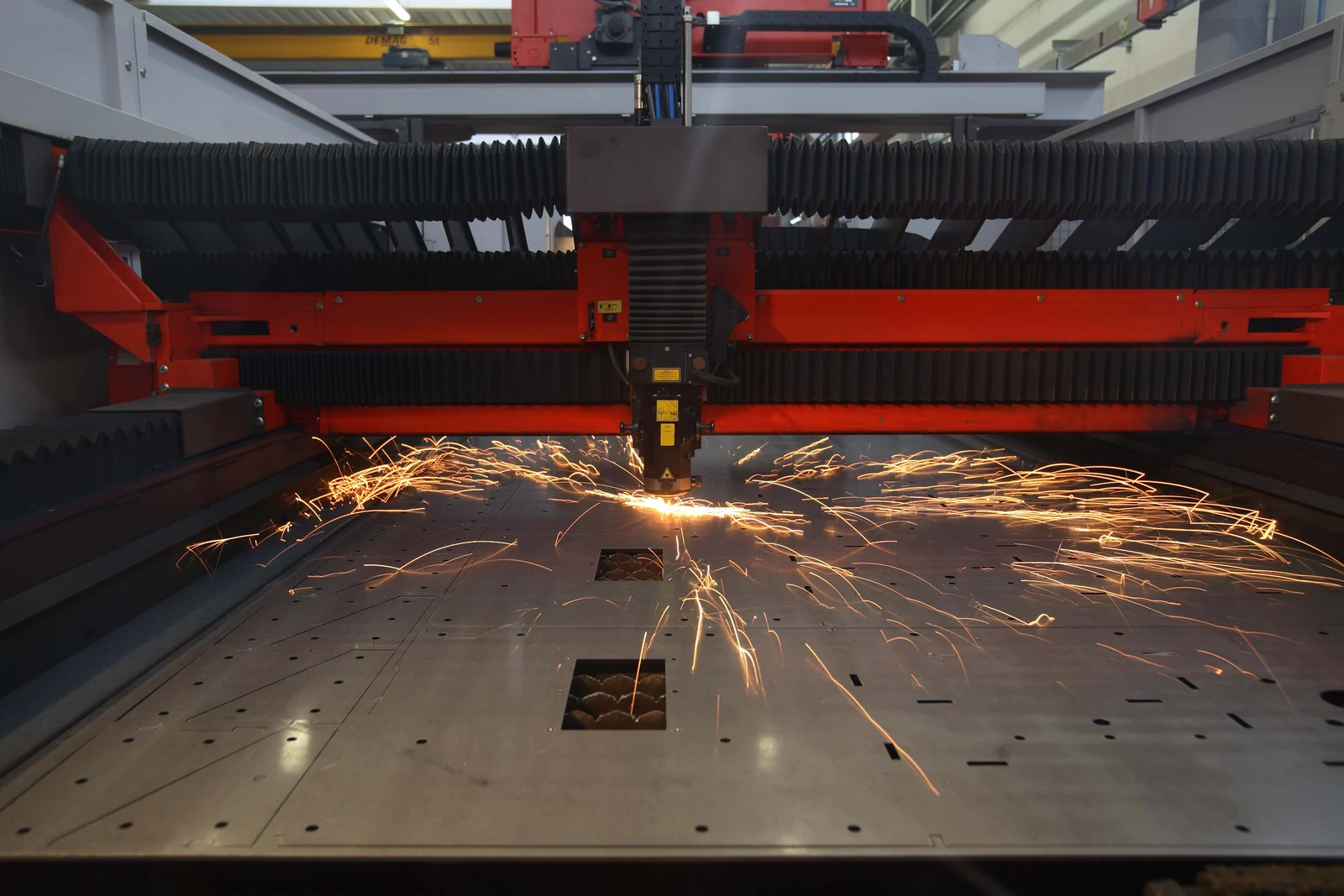
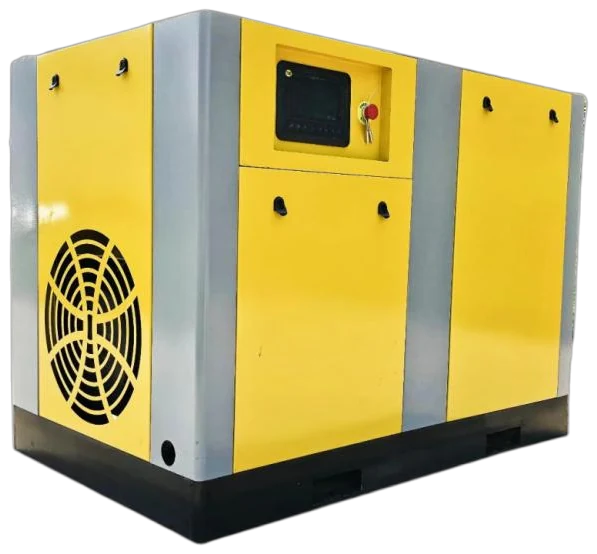
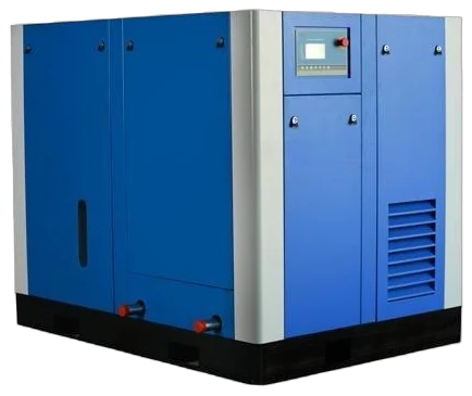
Complete compressed air system.
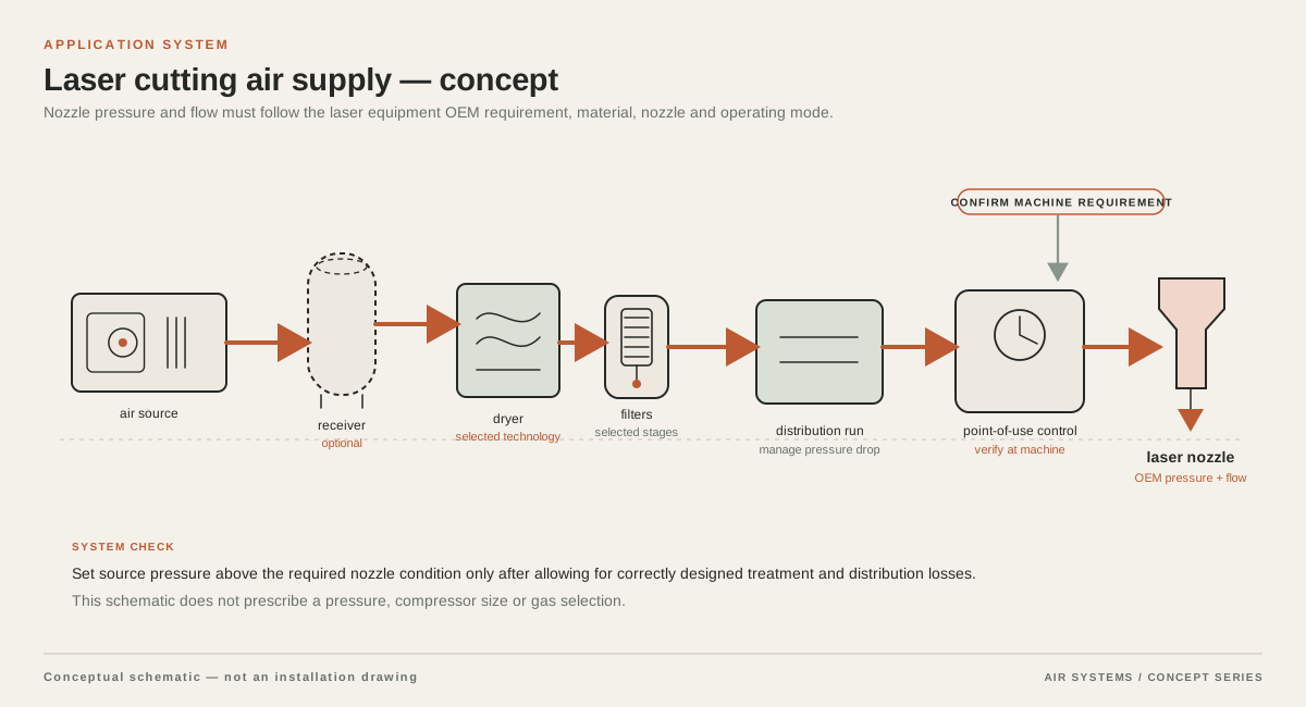
Combine compression, cooling, treatment, storage and distribution at the required pressure and point-of-use air quality. The layout below explains the system interfaces; it is not a photograph of an installed project.
DETAILED SELECTION & OPERATION
What compressed air does at the cutting head
Laser cutting concentrates heat at a small point until the workpiece melts or vaporizes. Assist gas is delivered through the cutting nozzle to eject molten material from the kerf, the narrow cut gap. It also affects cooling, oxidation and the stability of the cut. The gas jet must arrive at the head with enough pressure and flow after filters, dryer, pipework, valves and any receiver—not merely show a high pressure at the compressor outlet. TRUMPF’s laser-cutting explanation describes the gas as being emitted coaxially with the beam and notes that process gases are driven through the kerf at varying pressures.
Compressed air is not interchangeable with nitrogen or oxygen in every job. Gas choice changes the chemistry at the cut and the resulting edge, dross and oxidation. Air may be considered where the machine builder permits it and the material, thickness and finish tolerance are compatible. Stainless or other jobs requiring an oxide-free edge may call for an inert gas instead. Do not infer that an air compressor can replace all nitrogen or oxygen used at a facility; define the approved gas for each material and cut program.
- Treat the laser OEM’s gas inlet requirement as the process boundary.
- Separate the gas used for cutting from workshop air used for actuators, purge, cleaning or blow-off.
- Verify whether the stated pressure is gauge pressure at the machine connection or another reference point.
Start with the laser OEM process envelope
Do not size the compressor from laser source wattage alone. Request the laser model, cutting-head model and the OEM’s approved gas table or pre-installation document. The table should identify required inlet pressure range, flow or consumption, gas type, connection conditions, acceptable pressure fluctuation and the point where each value is measured. As one example of why this matters, a TRUMPF pre-installation manual gives machine-specific gas connection requirements; that document is evidence for that machine, not a universal requirement for every laser.
Capture the worst credible operating case rather than the average of easy cuts. List the thickest and most demanding material, the nozzle and orifice, the pressure setting, simultaneous heads if any, and the maximum number of machines that can cut together. Ask whether the OEM expresses flow as actual volume, standard volume or another basis. The RFQ should require bidders to state the same reference conditions and to show the pressure available at the laser inlet under the stated flow.
| Process item | Why it changes the air system | Evidence to request |
|---|---|---|
| Laser and cutting-head model | Controls approved gases, inlet limits and process tables | OEM gas specification or pre-installation document |
| Material, alloy and thickness range | Changes heat input, melt removal and gas demand | Production material schedule and representative cut programs |
| Nozzle type, diameter and stand-off | Changes jet shape, flow and cut quality | OEM nozzle chart and setup parameters |
| Pressure, flow and duty | Sets compressor, dryer, receiver and controls | Values at machine inlet, with units and reference basis |
| Required edge and oxidation result | Determines whether air is suitable at all | Quality acceptance sample or written process criterion |
Match air to material, nozzle and production duty
Material grade and thickness should be treated as primary selection inputs. Mild steel, stainless steel, aluminium and reflective non-ferrous alloys do not respond identically to heat and gas chemistry. Thickness also changes the melt-removal challenge. The peer-reviewed review of laser-cutting assist gas identifies assist pressure and nozzle geometry alongside material properties, cutting speed and beam parameters as process variables. It also reports that gas forces inside the kerf become especially important as thicker sections are processed. Use that evidence to justify an OEM-led process trial, not to promise a particular thickness or speed.
Nozzle diameter, alignment and stand-off influence the delivered jet. A larger opening may increase consumption, while a smaller orifice may impose a different pressure and flow relationship. The correct value is the one specified and validated for the head and program. Record intermittent piercing, contour cutting and long straight cuts separately. A compressor that meets a short peak can still fail if the receiver empties during repeated piercing or if the dryer and filters create excessive pressure loss during a sustained run.
- Provide a material-and-thickness matrix, including the percentage of production hours for each group.
- Identify the nozzle family, orifice, stand-off and pressure setting for the limiting program.
- Describe peak events such as piercing and whether another laser or pneumatic load can run concurrently.
- Define edge colour, dross, burr, roughness or oxidation criteria as process acceptance requirements.
Build the compressor, treatment and receiver as one system
A laser assist-gas system normally needs more than a compressor package. Depending on the OEM requirement and site air quality, the arrangement may include an intake, compressor, aftercooler, condensate management, particulate and coalescing filtration, dryer, receiver, pressure regulation, isolation valves and a clean distribution line to the machine. The treatment train must be selected for the required pressure, flow, moisture and contaminant limits. Do not describe a generic filter or dryer as proof that the gas meets the laser builder’s process requirement.
A receiver can buffer short demand changes and reduce control cycling, but it does not create compressor capacity. Its pressure rating, drain arrangement, inspection obligations and installation must comply with the applicable jurisdiction. Put the receiver and major treatment stages where maintenance access, condensate handling and safe isolation are practical. Ask suppliers to calculate pressure drop at the specified flow from the compressor discharge to the laser inlet, including dirty-filter allowance where relevant.
If the site has a shared plant-air ring, confirm whether its pressure, dew point and contamination history are compatible with the laser. A dedicated branch with local regulation and point-of-use filtration may be preferable when other users create fluctuations or contaminants. Conversely, a dedicated compressor can be inappropriate if the laser OEM requires a different gas or if the plant cannot provide the electrical, ventilation and maintenance conditions the package needs.
Control quality at the point of use
Specify air quality by measurable limits rather than labels such as clean air or laser grade. Ask for limits and test methods for particles, water and oil at the laser connection, plus the pressure dew point under operating conditions. A compressor technology label alone does not establish the quality at the nozzle: carryover, intake environment, pipe scale, filter condition, condensate and installation can all affect delivered gas. If the OEM gives a gas purity or dew-point requirement, reproduce that requirement in the RFQ and require evidence against it.
Pressure control should be assessed at the machine inlet while the cutting program is running. Include a regulator sized for the flow, a gauge or transducer at the relevant point and a defined response to low pressure or high temperature alarms. Do not use a nominal outlet pressure as a process guarantee. The laser controller may set recipe pressure, while the air system must maintain the required inlet conditions through the full demand profile.
When compressed air may be inappropriate
Compressed air should be ruled out when the laser OEM does not approve it, when the required edge must be oxide-free and the process calls for an inert gas, or when the site cannot achieve the specified moisture, contamination, pressure and flow conditions. It may also be unsuitable when the required peak demand makes the electrical, acoustic, ventilation or operating cost burden disproportionate. These are engineering decisions tied to the particular machine and product, not universal limits based on laser power.
If air is permitted, compare it with delivered or generated nitrogen and oxygen using the same cut samples and acceptance criteria. Include gas consumption, compressor energy, treatment replacement, downtime risk, storage, gas-changeover arrangements and the cost of rejected parts. A qualified trial should test the actual material and thickness mix. This page does not claim that any particular gas, compressor architecture or supplier will deliver a specified cut quality.
RFQ criteria for a laser-cutting air system
Ask each bidder to return a marked-up process basis, not just a motor rating and a catalogue flow. The comparison should show the guaranteed or quoted values at the agreed measurement point, with units, pressure basis, reference temperature and flow basis stated. Require exceptions to be visible: an item described as optional, subject to supplier confirmation or dependent on the OEM should not be treated as included performance.
The RFQ should also request a system drawing, utility schedule, noise and heat-rejection data, footprint, controls narrative, treatment consumables, commissioning tests and training scope. Define the acceptance test around the laser’s actual inlet conditions and representative cut programs. Obtain the laser OEM’s approval before purchase if the proposed arrangement changes gas type, connection, pressure regulation or treatment architecture.
- OEM laser and head documentation, approved gas, inlet pressure and flow range.
- Material grades, thicknesses, nozzle data, duty cycle, simultaneous loads and future expansion.
- Point-of-use particle, water and oil limits, pressure dew point and test method.
- Compressor type and capacity basis, treatment stages, receiver volume and safety compliance.
- Pressure-drop calculation from discharge to laser inlet at peak and continuous demand.
- Utilities, ventilation, ambient limits, controls, alarms, service access and commissioning plan.
- Explicit exclusions, supplier-confirmed options, warranty boundaries and required customer data.
Data to confirm before a quotation is accepted
A quotation should remain conditional until the laser builder or process engineer confirms the gas specification and the site confirms the duty profile. Ask for a written data-to-confirm schedule covering the items below. If a supplier cannot state a value, mark it as unknown rather than filling the gap with a typical number. This protects the cut process from a system that appears adequate at the compressor but fails at the nozzle.
The requested evidence should include the selected instruments’ calibration or verification approach, the location of pressure and quality measurements, and the commissioning record. Where a source gives an example value for one machine or research condition, do not transfer it to another laser without OEM confirmation.
- Laser OEM gas table and written permission to use compressed air for each relevant program.
- Flow units and reference conditions, inlet pressure basis, allowable fluctuation and measurement point.
- Nozzle and cutting-head configuration, material matrix, production schedule and quality limits.
- Site electrical, ambient, altitude, ventilation, piping route and shared-load information.
- Required air-quality limits, test certificates or commissioning measurements and re-test responsibility.
- Applicable receiver and pressure-equipment rules, drains, isolation and waste-condensate route.
SELECTION & OPERATION
Frequently asked questions
Can I size the compressor from my laser’s kilowatt rating?
No. Laser power is only one process variable. Use the OEM gas table together with material, thickness, nozzle, pressure, flow, duty cycle and simultaneous loads. The compressor must be checked for pressure and flow at the laser inlet after treatment and distribution losses.
Can compressed air replace nitrogen for every laser-cutting job?
No. Gas chemistry and the required edge or oxidation result determine whether air is acceptable. Obtain written OEM or process approval for each program and compare actual cut samples. Do not assume that an air system can replace all nitrogen or oxygen use.
Does an oil-free compressor automatically provide laser-quality air?
No. Compressor construction does not by itself prove point-of-use particle, water or oil limits. The complete treatment train, intake environment, piping, maintenance and test method must be matched to the laser OEM requirement.
What should be measured during commissioning?
Measure pressure and flow at the agreed laser connection while representative programs run, and verify the specified air-quality parameters using the agreed method. Record the active nozzle, material, thickness and duty so the result can be reproduced.
Technical references
- Laser cutting ↗
Assist gas ejects melt from the kerf; gas type and pressure, nozzle selection, material and thickness influence the process.
- Laser cutting basics: What is it and how it works ↗
The cutting head delivers assist gas through a nozzle; compressed air, nitrogen and oxygen have different process roles.
- Laser Cutting: A Review on the Influence of Assist Gas ↗
Peer-reviewed discussion of assist pressure, nozzle geometry, material thickness, gas dynamics and their relationship to melt removal and cut quality.
- Operator's manual TruLaser 2030 (L82) ↗
Illustrates that gas connection requirements are machine-specific and must be taken from the applicable OEM pre-installation documentation.