Complete compressed air system.
Combine compression, cooling, treatment, storage and distribution at the required pressure and point-of-use air quality. The layout below explains the system interfaces; it is not a photograph of an installed project.
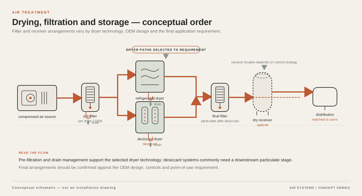
DETAILED SELECTION & OPERATION
What a compressed-air filter is expected to remove
Filtration addresses specific entrained contaminants. A particulate filter is intended to retain solid particles within its tested range. A coalescing filter is used to remove liquid aerosols and oil aerosols by combining fine droplets so they can drain from the element. Bulk liquid separation, drying and adsorption are different treatment duties and should not be assumed to occur simply because a filter is installed. The air-quality target should therefore name the contaminant, concentration or particle-size concern and measurement point.
ISO 12500-1 describes a test layout for coalescing filters that determines oil-aerosol removal effectiveness and reports pressure-drop and outlet oil-aerosol characteristics under stated rating conditions. ISO 12500-3 addresses particulate removal testing by particle-size range. These standards describe test methods; they are not a blanket approval of any unverified filter assembly or a promise of clean air at every operating condition.
- Coalescing filtration: address liquid water and oil-aerosol loading, drainability and pressure drop.
Choose the element by process risk, not the finest nominal number
Start with the process consequence of contamination. A general pneumatic circuit may prioritize reliable particulate and condensate control. Paint, instrumentation, laboratory, food-contact or packaging uses may require tighter limits and documented verification at the point of use. The required outcome should be written in measurable terms where possible, such as particle-size bands, liquid carryover, oil-aerosol concentration, pressure dew point and sampling location. A nominal pore or micron description without a test basis is not enough to compare offers.
A tighter element can increase resistance, especially as it loads. A larger housing or parallel arrangement may reduce velocity and preserve usable pressure, but it changes footprint, cost and maintenance. Ask suppliers to state the flow basis, inlet pressure, inlet temperature, relative humidity or liquid loading assumptions and clean-versus-loaded pressure drop. Do not compare pressure-drop values taken at different air bases as if they were equivalent.
| Decision area | What to define | Evidence to request |
|---|---|---|
| Contaminant | Solid particles, bulk liquid, oil aerosol or a combination | Test method, rated removal result and sampling basis |
| Flow and loading | Normal, peak and turndown flow with inlet conditions | Capacity curve and clean/loaded pressure-drop data |
| Air-quality endpoint | Required quality at outlet or point of use | Validation plan and component or assembly documentation |
| Drain and service | Automatic/manual drain, access and isolation arrangement | Drain operating limits, element-change method and spares |
Pressure drop is an operating requirement
Pressure drop is the loss between the filter inlet and outlet at a stated flow and condition. It consumes the pressure margin available to the machine, regulator or process. The loss can rise as the element loads with solids or liquid, so a selection based only on initial pressure drop may understate the operating problem. Install inlet and outlet gauges or another suitable differential indication when the duty justifies it, and define the intervention point with the supplier and site maintenance team.
Capacity must be checked at the real minimum inlet pressure and maximum expected flow, not only at a catalogue reference point. Intermittent peaks from blow-off, valve banks or production changeover can momentarily exceed the average compressor flow. A filter acceptable at average demand may produce unacceptable transient loss when undersized. Parallel housings, a larger connection or local storage can be considered, but the complete arrangement needs pressure, drain and isolation review.
Coordinate filters with the compressor, dryer and receiver
A filter train works only when its sequence matches the contamination load. A receiver may provide a location for bulk condensate management and buffering, but it does not replace filtration or drying. A refrigerated or desiccant dryer has its own allowable inlet conditions and pressure-drop characteristics. Upstream separation can reduce liquid loading, while downstream filtration may protect a sensitive user. The exact order depends on the compressor technology, ambient conditions, dryer design and required air quality.
Place drains where separated liquid can be safely removed and inspected. Protect elements from reverse flow, uncontrolled bypass and water hammer where relevant. Provide isolation and depressurization provisions so an element can be serviced without exposing personnel to trapped pressure. If a bypass is required for continuity, its status and air-quality consequence should be visible; an open bypass can defeat the intended treatment.
Plan maintenance around loading and duty
Element life depends on particulate loading, liquid carryover, oil carryover, flow profile, ambient conditions and the chosen element. There is no universal replacement interval that can be responsibly promised without supplier and site data. Use differential pressure, visual inspection, drain performance and process quality checks to establish a maintenance trigger. A calendar interval can supplement those checks only after the operating duty is known.
After maintenance or a process change, verify the outlet at the defined sampling point. A filter-element certificate, where supplied, is not by itself evidence that the complete installed train meets an end-use requirement. Food, pharmaceutical, breathing-air, sterile or hazardous applications need their own applicable validation and regulatory review.
Configuration items to mark standard or optional
A quotation should identify what is included and what is optional rather than leaving treatment assumptions hidden in a filter label. Depending on the proposed configuration, a housing may be offered with an element, differential-pressure indicator, drain, wall or floor mounting, isolation valves, bypass, spare element and documentation package. None of those items should be treated as available or standard until the supplier confirms the exact assembly.
| Item | Often considered | Confirm before purchase |
|---|---|---|
| Housing and element | Housing with selected element | Material, seal, connection, pressure/temperature limits and exact element code |
| Drainage | Manual or automatic drain | Drain type, operating range, failure mode and discharge arrangement |
| Monitoring | Differential-pressure indicator or gauge | Scale, alarm/contact option, mounting and calibration expectations |
| Installation | Isolation, bypass and supports | Included valves, flow direction, service clearance and safe depressurization |
| Documentation | Data sheet and maintenance instructions | Test basis, certificates, curves, spares list and acceptance checks |
RFQ data required for a defensible filter offer
Send the supplier a process description and a simple air-system sketch showing compressor discharge, receiver, dryer, main header, branch users and proposed sampling points. State normal and maximum flow, minimum and maximum inlet pressure, inlet temperature, ambient range, relative humidity, compressor type and oil-injection status. Identify whether the flow is continuous, cyclic or peak-driven. These data allow capacity and pressure-drop claims to be compared on the same basis.
Define the contamination target separately for each location. Include particle-size concern, liquid water, oil aerosol or vapour, rust or pipe scale, and any process-specific limit. State whether the target applies at the filter outlet, the machine inlet or the actual point of use. Ask for the proposed stage sequence, clean and loaded pressure drop, rated flow basis, drain arrangement and element-change criterion.
- Required quality target and measurement point.
- Normal, peak and minimum-flow conditions.
- Pressure, temperature, humidity and compressor technology.
- Contaminant type, loading estimate and condensate chemistry.
- Dryer, receiver and upstream/downstream treatment arrangement.
- Pressure-drop limit, monitoring method and maintenance trigger.
- Required certificates, validation documents and jurisdictional requirements.
When a compressed-air filter is the right answer
Filtration is appropriate when the problem is a defined solid, liquid or oil-aerosol contaminant and the process can accept the filter’s verified capacity and pressure loss. It is often one part of a treatment train for pneumatic equipment, instrumentation, manufacturing machinery and protected process branches. The selection should be tied to the actual quality target and checked after installation.
Filtration alone is inappropriate when the requested result is a lower pressure dew point, removal of dissolved vapour, sterile or breathing-air approval, or a universal guarantee of zero contamination. It is also a poor response to a leaking distribution system, undersized compressor or incorrect pressure setting. Those problems need separate diagnosis. For food and other regulated uses, oil-free compression, treatment, point-of-use filtration and end-product risk controls must be evaluated together; an air filter label is not a food-safety assurance.
SELECTION & OPERATION
Frequently asked questions
Do compressed-air filters remove water from the air?
A suitable separator or coalescing filter can remove entrained liquid water under its stated operating conditions, but it does not replace a dryer for controlling water vapour or pressure dew point. Confirm liquid loading, drain performance, flow and the required measurement point with the supplier.
Is a smaller micron rating always a better filter?
No. The particle-size test basis, contaminant type, flow, pressure drop and loading behaviour matter more than an isolated nominal number. A finer element may add resistance or require more frequent service, so compare verified performance at the actual air conditions.
Where should a coalescing filter be installed?
Its position depends on the compressor, receiver, dryer, condensate load and required air quality. It may be used upstream or downstream of a dryer and may be supplemented by a point-of-use stage. The supplier should confirm sequence, drainage, flow direction, isolation and pressure-drop implications for the complete train.
Does ISO 12500 certification prove my installed air is compliant?
No. ISO 12500 provides filter test methods and performance presentation for defined conditions. A test result for an element or housing does not automatically validate the complete assembly, installation, maintenance state or point-of-use air quality. Request application-specific evidence and verification.
Technical references
- ISO 12500-1:2007 - Filters for compressed air — Test methods — Part 1: Oil aerosols ↗
Scope of coalescing-filter test layout, oil-aerosol removal effectiveness, pressure-drop characterization and outlet oil-aerosol reporting under stated rating parameters.
- ISO 12500-3:2009 - Filters for compressed air — Test methods — Part 3: Particulates ↗
Particle-size-based particulate removal test methods and the distinction between fine and coarse filter ranges.
- CAGI Electrical Handbook, Chapter 8: General Reference Data ↗
Compressed-air terminology including pressure drop as loss caused by restriction or friction in a system component.