INDUSTRIAL COMPRESSOR EQUIPMENT

20 Bar Air Compressors

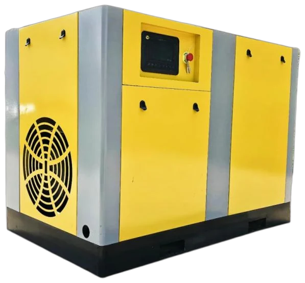
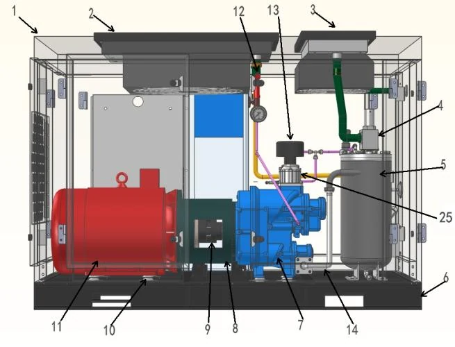
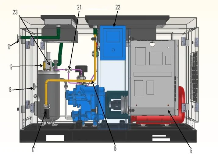
The yellow enclosure photograph is a Dezhou YITong electric medium/high-pressure series reference. It has no readable model or pressure nameplate, so it is not presented as a photograph of a listed 20 bar model. The blue enclosure remains a secondary series reference, while the two detail assets are supplier catalogue structure diagrams rather than equipment photographs. Select the exact 20 bar configuration only from the confirmed quotation and its system scope.

  • 20 bar (2.0 MPa) electric catalogue model examples
  • High-pressure series reference photograph — not a specific 20 bar model
  • Supplier catalogue structure diagrams, not internal-equipment photographs
  • Cooling, treatment, storage and controls defined for the confirmed duty
01

20 bar electric model examples from the supplier catalogue

The model table above is drawn from the Dezhou YITong electric medium/high-pressure selection catalogue. Every displayed row combines a `/20` model code with a source-table pressure entry of 2 or 2.0 MPa. For customer comparison, that pressure is expressed as 20 bar (2.0 MPa). The examples include EBLW entries at 1, 2 and 3 m³/min nominal flow and EBLGII entries from 3.5 to 33 m³/min nominal flow.

Use these as catalogue model examples, not as an unqualified package specification. The table preserves the catalogue's nominal m³/min designation and does not relabel it as FAD. Its motor figures are rated motor power; auxiliaries, controls and cooling can change the electrical boundary of the complete package. The quotation should restate delivered flow, pressure, test conditions and included scope for the selected configuration.

  • Pressure shown for this page: 20 bar (2.0 MPa).
  • Catalogue designations represented: EBLW and EBLGII electric medium/high-pressure models.
  • Catalogue nominal flow is kept in m³/min and is not presented as FAD.
  • The exact offered model, cooling method, drive and package scope belong in the quotation.

EQUIPMENT CONFIGURATIONS

Compare the series specifications.

Compare the listed pressure and flow basis, then send the application and operating profile for a matched quotation.

20 Bar (2.0 MPa) Electric Compressor Model Examples
Catalogue modelRated motor power (kW)Nominal volumetric flow (m³/min)Catalogue pressure
EBLW-1/20-11Kw11120 bar (2.0 MPa)
EBLW-2/20-18.5Kw18.5220 bar (2.0 MPa)
EBLW-3/20-30Kw30320 bar (2.0 MPa)
EBLGII-3.5/20-30Kw303.520 bar (2.0 MPa)
EBLGII-8/20-55Kw55820 bar (2.0 MPa)
EBLGII-6/20-55Kw55620 bar (2.0 MPa)
EBLGII-10/20-90Kw901020 bar (2.0 MPa)
EBLGII-20/20-160Kw1602020 bar (2.0 MPa)
EBLGII-24/20-200Kw2002420 bar (2.0 MPa)
EBLGII-28/20-250Kw2502820 bar (2.0 MPa)
EBLGII-30/20-250Kw2503020 bar (2.0 MPa)
EBLGII-33/20-280Kw2803320 bar (2.0 MPa)

Catalogue basis: Dezhou YITong electric medium/high-pressure selection catalogue, pages 5–8. Pressure is shown as 20 bar (2.0 MPa); flows retain the catalogue's nominal m³/min designation and are not FAD; motor rating is not package electrical input power.

Source: Dezhou YITong Electric Medium/High-Pressure Selection Catalogue (电动中高压选型手册-.pdf) · pp. 5, 6, 7, 8. Final model duty and supply scope are stated in the quotation.

02

20 bar model structure: family-level design information

The supplier manual describes more than one compression arrangement within its medium/high-pressure family; a 20 bar label does not identify one universal internal design. It describes 1, 2 and 3 m³/min models as twin-screw-and-scroll arrangements. For the 4, 5 and 6 m³/min family it describes either a parallel small-displacement arrangement or a combination of two twin-screw units with one single-screw unit. For models at 23 m³/min and above, it describes a two-stage twin-screw-and-scroll arrangement. Other regular models are described at family level as single-screw or twin-screw constructions.

That description supports a structural comparison, but it does not assign every construction detail to every individual model in the 20 bar table. Request the exact compression arrangement, stages, cooling layout and lubricant circuit for the offered model. The source range is lubricated/oil-injected compression equipment; downstream treatment can be specified for the required air quality, but this does not turn the compressor into an oil-free machine or establish point-of-use purity.

How the supplier manual groups compression structures
Catalogue flow groupingFamily-level structure described in the manualHow to use it for a 20 bar RFQ
1, 2 and 3 m³/minTwin-screw-and-scroll arrangementIdentify the exact EBLW model, cooling option and delivered-flow basis.
4, 5 and 6 m³/minParallel small-displacement arrangement, or two twin-screw units plus one single-screw unitAsk which of the stated arrangements applies to the offered unit.
23 m³/min and aboveTwo-stage twin-screw-and-scroll arrangementConfirm stages, interstage/cooling scope and the rated pressure boundary.
Other regular modelsSingle-screw or twin-screw constructionRequest the model-specific construction drawing and maintenance points.

COMPONENT ARRANGEMENT

Package components.

Catalogue structure diagrams show the arrangement of compression, controls and cooling. Check clearances and installation scope for your chosen configuration.

High-pressure compressor catalogue structure diagram showing motor, compression unit and piping.
Product structure diagramCatalogue structure diagram. Confirm the selected package layout.
High-pressure compressor catalogue diagram showing controls, oil filter and piping layout.
Product structure diagramCatalogue structure diagram. Confirm the selected package layout.
03

Specify the 20 bar package and treatment as one pressure-rated system

A 20 bar compressor alone does not define the air available at a machine. State the required pressure at the point of use, then allow for the actual losses through the aftercooler, moisture separator, dryer, filters, receiver, valves, piping and final regulator. The quotation should identify the design pressure and temperature basis for every pressure-containing component, including receiver, treatment equipment, hoses and fittings—not only the compressor discharge label.

The supplier manual lists air-cooled and water-cooled alternatives and a separate aftercooler option for this family. Treat those as configuration choices to be stated in the offered scope, not as standard inclusions. Select drying, filtration and drains from the required point-of-use particle, water and oil limits, actual inlet conditions and allowed pressure loss. A filter or dryer pressure rating does not by itself demonstrate the rating of the assembled system.

20 bar system arrangements to compare in an RFQ
ArrangementWhen it may fitWhat the quotation should define
Dedicated 20 bar compressor branchA sustained high-pressure demand or several coordinated high-pressure usersSelected model, delivered flow, cooling, controls, treatment, receiver and high-pressure distribution boundary
Lower-pressure source plus boosterA localized high-pressure user with intermittent or limited demandBooster inlet requirement, base-system capacity, peak recovery, branch storage and switching sequence
Sequenced high-pressure packagesA duty/reserve requirement or a load profile that justifies staged operationLead/lag logic, standby duty, pressure band, alarms and each package's scope
04

Applications where a 20 bar branch may be evaluated

A 20 bar branch should be tied to a documented process requirement rather than used as a higher-pressure substitute for ordinary plant air. Suitable starting cases are an OEM-defined high-pressure blowing or forming step, a controlled test or leak-test duty, or a dedicated process/actuator branch that explicitly requires this pressure range. In each case, obtain the OEM's pressure tolerance, required flow, air-quality limit and duty profile before choosing direct compression or a booster arrangement.

For PET bottle blowing, separate the high-pressure blowing event from the lower-pressure auxiliary air used by controls, conveyors or other packaging functions. The machine maker's specification remains decisive: this page does not state that every PET system operates at 20 bar. Review the related PET bottle blowing system page and packaging air page alongside the machine documentation.

  • High-pressure process air only where the equipment documentation specifies the pressure and flow.
  • Short, repeated test or blow events only after storage and recovery are calculated.
  • Separate high-pressure and general plant-air zones where the duty supports that layout.
05

Installation checks and maintenance basis

Before installation, define electrical supply, ventilation or cooling-water interfaces, heat rejection, condensate handling, service access, lifting and foundation needs. The final layout should show isolation, non-return protection, relief protection, drains, gauges and safe access to filters, coolers and the receiver. Confirm local pressure-vessel and piping obligations with the responsible project team and authority.

Use the offered equipment's operation and maintenance documentation for service intervals. At routine inspections, include drains, filter differential pressure, cooler cleanliness, leaks, instrument readings and protective-device checks within the OEM and site safety plan. For concise common methods, use the pressure selection guide, flow-basis guide, pressure-drop guide and air receiver sizing guide instead of relying on an unqualified universal schedule.

Complete compressed air system.

Combine compression, cooling, treatment, storage and distribution at the required pressure and point-of-use air quality. The layout below explains the system interfaces; it is not a photograph of an installed project.
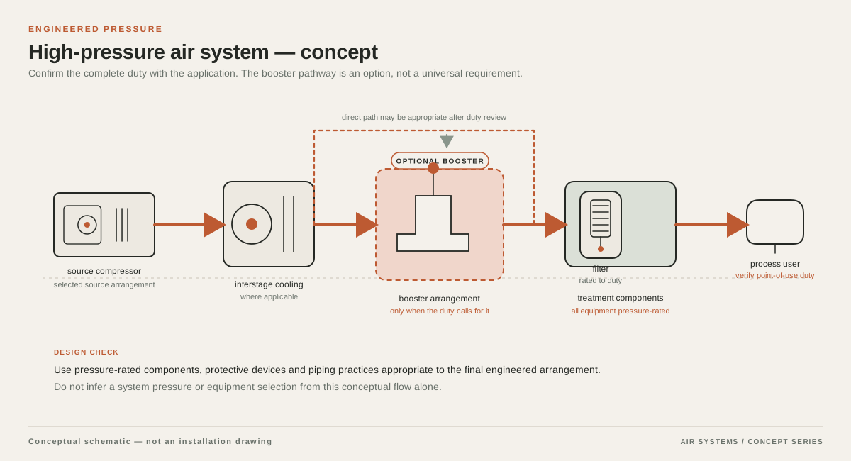
Conceptual supply arrangement for 20 Bar Air Compressors
System schematic. Component sequence depends on the selected equipment and duty.

DETAILED SELECTION & OPERATION

06

Separate continuous flow from short 20 bar events

For a continuous 20 bar load, compare a dedicated high-pressure package against the required delivered flow at the agreed pressure and rating conditions. Do not choose from the catalogue nominal-flow number alone. Confirm minimum pressure at the machine, normal flow, process hours, control range, cooling conditions and the consequences of an unload, trip or maintenance event.

For intermittent demand, record each event's flow, duration, repetition rate and acceptable recovery time. A lower-pressure plant with a booster and local high-pressure receiver can be worth comparing where the duty is confined to one branch, but the upstream system must withstand booster inlet demand without disrupting other users. A receiver can buffer a short event; it cannot provide continuous compressor capacity.

  • Log normal and peak flow separately, with one stated reference basis.
  • Record the low-pressure inlet behaviour if a booster is considered.
  • Place the pressure measurement point at the critical machine, not only at the compressor outlet.
  • Define the recovery time and the permitted pressure band after each event.
07

Teaching example: framing a 20 bar selection without choosing a model

The figures below are teaching assumptions only, not a project specification or a model recommendation. Assume all flow figures share one hypothetical reference condition; they are not claimed as FAD or as the catalogue's nominal-flow basis. The exercise shows why a time-average flow, peak flow and pressure-drop budget must be kept separate.

The assumed 18.5 bar(g) minimum at the machine plus 0.3 bar treatment loss and 0.7 bar distribution/event allowance gives a 19.5 bar(g) source target before control tolerance is considered. That makes a nominal 20 bar (2.0 MPa) system a candidate for investigation, but it does not prove that any listed model will deliver the duty. The supplier must verify the complete pressure band, delivered flow and recovery with its selected controls and receiver arrangement.

Teaching-only 20 bar selection assumptions
ItemAssumptionCalculation or implication
Point-of-use pressureMinimum 18.5 bar(g) at one machineUse the machine connection as the reference point.
Pressure allowance0.3 bar through treatment; 0.7 bar through distribution during the event18.5 + 0.3 + 0.7 = 19.5 bar(g) before control tolerance.
Continuous flow1.2 m³/minBase demand is present throughout the example cycle.
Short additional event0.8 m³/min for 15 seconds every 120 secondsTime-average addition = 0.8 × 15 ÷ 120 = 0.1 m³/min.
Average and peak flowSame hypothetical reference condition for all flowsAverage = 1.2 + 0.1 = 1.3 m³/min; simultaneous peak = 1.2 + 0.8 = 2.0 m³/min.
Selection stepNo catalogue model is selectedCheck high-pressure receiver storage and recovery, then obtain supplier-delivered-flow data at the agreed basis.
08

Data needed for a 20 bar quotation

Give every bidder the same process boundary. State whether 20 bar is gauge or absolute pressure, where it is measured, the minimum/normal/maximum pressure band, and the pressure permitted during a transient. Separate continuous demand from peak events and identify the flow reference conditions. Ask for the direct-compression and booster alternatives only where both are technically relevant to the duty.

Request a line diagram and a clear inclusions schedule covering compression, cooling, separation, drying, filtration, receiver, drains, controls, relief protection and distribution interfaces. Ask the bidder to identify the exact model, rated motor power, complete-package electrical boundary, cooling duty, treatment pressure loss, maintenance scope and conditions used for delivered-flow data.

  • Machine OEM pressure, flow, air-quality and transient-duty requirements.
  • Ambient conditions, altitude, voltage/frequency, cooling availability, layout and noise constraints.
  • Receiver design pressure, volume, drains, relief devices and applicable inspection requirements.
  • Acceptance measurement points, flow basis, stabilization conditions and responsibilities.

SELECTION & OPERATION

Frequently asked questions

Which 20 bar compressor models are shown on this page?

The clean table presents verified catalogue rows with `/20` model codes and a 2 or 2.0 MPa source-table pressure entry. It includes EBLW examples at 1, 2 and 3 m³/min nominal flow and EBLGII examples from 3.5 to 33 m³/min nominal flow. It is a catalogue comparison, not a stock or lead-time statement.

Is 20 bar the same as 2.0 MPa in this model table?

Yes. This page displays the catalogue's 2 or 2.0 MPa entries as 20 bar (2.0 MPa). The project specification must still state whether the required operating pressure is gauge or absolute and identify the measurement location.

Are the listed m³/min figures FAD?

No. They retain the supplier catalogue's label of nominal volumetric flow in m³/min. The table does not call them FAD. Before comparing an offer with process demand, obtain the supplier's flow basis, reference conditions and delivered-flow information at the specified duty.

Do all 20 bar models use the same compression structure?

No. The manual describes several family-level structures, including twin-screw-and-scroll arrangements for the 1, 2 and 3 m³/min grouping and a two-stage twin-screw-and-scroll arrangement for models at 23 m³/min and above. It does not assign every individual 20 bar model a complete construction drawing, so request that information for the quoted unit.

Should a 20 bar process use a dedicated compressor or a booster?

Compare a dedicated branch where high-pressure flow is sustained or shared by several users with a lower-pressure source and booster where the demand is localized or intermittent. The decision depends on inlet stability, peak/recovery profile, storage, cooling, treatment, controls and the complete pressure boundary—not on pressure label alone.

Technical references

  1. Dezhou YITong electric medium/high-pressure selection catalogue ↗

    Supplier catalogue source for the listed electric medium/high-pressure model examples, nominal-flow designation, pressure entries and family-level structure description.

  2. CAGI Performance Verification Program ↗

    Why a buyer should request comparable performance data and a stated test basis rather than rely on an unqualified flow number.

  3. Improving Compressed Air System Performance — U.S. Department of Energy ↗

    General system context for demand profiles, storage, treatment and distribution; it is not used as a model-performance guarantee.

PROJECT QUOTATION

Specify your air system.

Send the working pressure, air demand and operating conditions. We will help select equipment and system components for your process.

Send your project requirements ↗