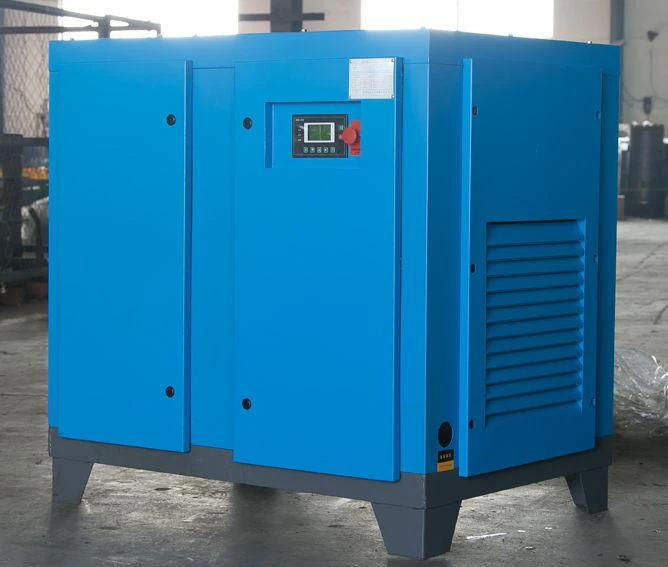
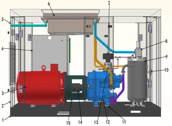
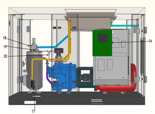
Complete compressed air system.
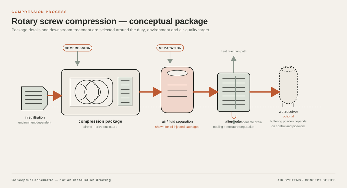
Combine compression, cooling, treatment, storage and distribution at the required pressure and point-of-use air quality. The layout below explains the system interfaces; it is not a photograph of an installed project.
DETAILED SELECTION & OPERATION
What fixed-speed means in a screw compressor
In a fixed-speed rotary screw compressor, the drive motor operates at a nominal constant speed while the control system changes how much air is admitted, compressed, or delivered. Common control approaches discussed by the Compressed Air and Gas Institute include modulation and online/offline, also called load/unload, operation. A fixed-speed designation therefore describes the drive arrangement, not a guaranteed operating point, efficiency, pressure, or flow rate. Those values must be confirmed against a supplier data sheet at stated inlet conditions and discharge pressure.
The distinction matters at part load. A compressor may remain energized while delivering less air, or unload while waiting for system pressure to fall. Frequent transitions make the control and receiver arrangement important. Compressed Air System Controls and the U.S. Department of Energy sourcebook provide background on these choices.
When a fixed-speed arrangement is a good fit
A fixed-speed configuration is worth evaluating when the plant has a broad, predictable base load and the compressor can spend substantial operating time near its selected capacity. Examples may include a process line that runs on a repeatable shift pattern, a dedicated machine group with limited variation, or a lead compressor in a multi-unit system where another unit handles trim demand. These are application patterns, not claims that a fixed-speed package is automatically the lowest-cost option.
It is less attractive when demand changes sharply, the plant operates for short intermittent bursts, or the compressor is substantially oversized because peak demand was mistaken for continuous demand. In those cases, compare fixed-speed control behavior with a variable-speed alternative, staged compressors, additional storage, or a sequenced system. The comparison should use measured demand and part-load data rather than a motor-kilowatt label alone.
- Potentially suitable: stable base flow, long runs, and a defined pressure band.
- Requires closer review: two or more shifts with different production rates, large blow-off events, or standby equipment that is rarely loaded.
- Potentially inappropriate as a sole unit: highly intermittent demand with little storage and strict pressure stability at the point of use.
Control method and receiver relationship
Ask the supplier to identify the proposed individual control method, including whether the arrangement is modulation, load/unload, or another manufacturer-specific strategy. Explain how the controls respond to falling demand, what the minimum stable operating condition is, and how the package handles unloaded periods. Do not assume that every fixed-speed screw compressor has the same turndown behavior or the same restart limits.
Storage is part of the control design, not an afterthought. A receiver can provide a pressure buffer for short demand events and give a load/unload system time to change state, but it does not create compressor capacity for a sustained deficit. Request the proposed receiver volume, pressure rating, drain arrangement, and location, then check that the vessel and installation meet the applicable local pressure-equipment rules. A second receiver near a fluctuating load may serve a different purpose from a central receiver; the piping and pressure-drop assessment should show why.
Selection tradeoffs beyond motor size
Start with required flow at the actual point of use and separate continuous demand from short peaks. Record the minimum, normal, maximum, and transient flow, plus operating hours and production changes. Then establish the pressure needed at the critical user, not merely the compressor discharge set point. Filters, dryers, valves, hoses, headers, elevation, and local regulators can consume pressure between the package and the tool or process. A larger pressure set point used to hide distribution losses can increase energy use without correcting the underlying restriction.
Compare package boundaries carefully. A quotation may include only the compressor or also a starter, controller, aftercooler, receiver, dryer, filters, and condensate management. Require a line-by-line inclusion schedule.
| Item | Engineering question | Supplier confirmation required |
|---|---|---|
| Capacity control | How is output reduced at part load, and what happens during an unload period? | Control type, operating sequence, limits, and control diagram. |
| Rated flow and pressure | At what reference conditions and discharge pressure are values reported? | Test basis, tolerances, performance data, and guaranteed duty point, if offered. |
| Storage | Is the receiver buffering short peaks, supporting control transitions, or both? | Volume, design pressure, code documentation, drains, and included scope. |
| Air treatment | What pressure dew point and contaminant control does the process require? | Dryer, filters, drains, pressure loss, and maintenance requirements. |
| Installation | Can the room provide cooling air, service access, power, and safe condensate handling? | Heat rejection, electrical data, clearances, noise data, and layout drawings. |
Use the operating profile to choose one unit or a system
A single fixed-speed compressor should not be sized from the largest connected nameplate total. Build a demand profile from flow measurements, production records, or a documented engineering estimate. Identify the base load, the duration and frequency of peaks, and the consequence of pressure variation. For a plant with a steady base and variable trim, a fixed-speed lead unit may be evaluated alongside a variable-speed or smaller staged unit. For multiple fixed-speed units, ask how the master controller sequences them and how it prevents unnecessary parallel unloading.
Redundancy is separate from capacity. State whether the required duty is N, N+1, or another arrangement, which loads may be curtailed, and whether standby rotation, isolation, and condensate routing are included. No uptime claim should be inferred from the product category.
Installation, treatment, cooling, and maintenance
A fixed-speed package still needs a properly designed compressor room. Verify intake-air cleanliness, ambient range, ventilation, heat rejection, service clearances, electrical supply, lifting access, and protection from water or corrosive contaminants. If enclosed, ask how cooling air moves and whether recirculation could raise inlet temperature. The supplier should identify site derating or operating limits.
Choose treatment from the end-use requirement. An aftercooler and separator may remove much of the heat and bulk condensate, while a dryer and correctly selected filters address moisture and particulate or oil carryover requirements. Treatment adds pressure loss and maintenance points. Ask for pressure-drop data at the requested flow and for a condensate-management scheme. Maintenance intervals depend on the OEM design, ambient conditions, air quality, and duty cycle; obtain the actual service schedule rather than inserting a universal interval into the RFQ.
RFQ information for a fixed-speed screw compressor
A useful RFQ lets suppliers compare the same duty. Describe air use, hours, shifts, elevation, ambient range, voltage and frequency, critical-user pressure, and the required air-quality class or process limit. Provide measured flow if available and label each value as actual, standard, normal, or another reference basis. Do not mix free-air delivery, inlet volume, and normalized flow without stating reference temperature, pressure, humidity, and units.
Request a proposed fixed-speed configuration, not an assumed product. Ask for the control sequence, part-load data, receiver and treatment selections, pressure-drop assumptions, noise and heat-rejection data, dimensions, connections, starting characteristics, service access, warranty, exclusions, lead time, and compliance documentation. Mark each value as guaranteed, calculated, typical, or to be confirmed.
- Demand: minimum, average, peak, duration, simultaneity, and future expansion allowance.
- Pressure: minimum point-of-use pressure, distribution losses, receiver pressure band, and relief settings.
- Site: altitude, ambient range, cooling-water or air-cooled conditions, power quality, room constraints, and hazardous-area restrictions if applicable.
- Scope: compressor, motor control, receiver, dryer, filters, drains, piping, commissioning, training, spares, and service.
- Evidence: performance test basis, drawings, manuals, certificates, and the data still pending confirmation.
Data-to-confirm notice
Any fixed-speed compressor discussed here is for engineering comparison. Obtain a supplier quotation and submittal confirming flow, pressure, controls, motor, treatment, receiver, compliance, service, lead time and exclusions. A component certificate is not approval of the complete assembly.
SELECTION & OPERATION
Frequently asked questions
Are fixed-speed screw compressors always more efficient than variable-speed compressors?
No. A fixed-speed unit may fit a stable base load, but part-load losses depend on the design and demand profile. Compare duty-point and part-load data for the complete system, including storage and treatment.
Does a fixed-speed compressor deliver a constant flow?
No. The motor is nominally constant-speed, while inlet, load/unload, or other controls change delivered capacity. Confirm the actual flow range and pressure response.
How much receiver capacity is required with a fixed-speed screw compressor?
There is no universal size. Selection depends on control method, capacity, pressure band, allowable variation, peak duration, and central or local storage. Ask the supplier to show the receiver's purpose and verify local rules.
Can I select a fixed-speed compressor from motor kW alone?
No. Motor size does not establish delivery, pressure capability, air quality, part-load behavior, or site suitability. Base the RFQ on flow and pressure at explicit reference conditions, then confirm scope.
Technical references
- Compressed Air System Controls Technical Brief ↗
Terminology and comparison of rotary compressor capacity-control methods, including modulation and online/offline operation.
- Improving Compressed Air System Performance: A Sourcebook for Industry ↗
General compressed-air system guidance on compressor controls, storage, demand, and system-level selection; used here without treating any supplier model or performance value as verified.